


17 / 60
MKE Synchronous Servomotors
Features and functions
Bosch Rexroth AG
R911414374, Edition 01
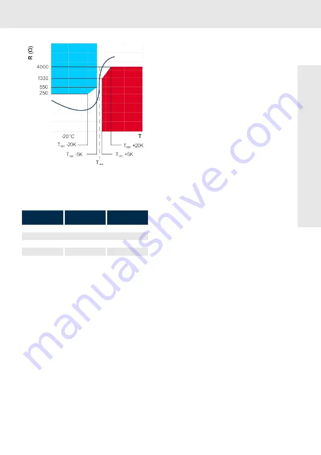
Fig. 2: Temperature-resistance-diagram
according to EN 60034-11:2004, DIN
44082:1985-06 Thermistors; PTC for thermal
machine protection; climate category HFF
Temperature range Resistance
Measuring voltage
[V
DC
]
-20
°C to T
REF
-20K 20
Ω
to 250
Ω
≤
2.5
V
Temperature range 90 °C - 160 °C
T
REF
-5K
≤
550
Ω
≤
2.5
V
T
REF
+5K
≤
1330
Ω
≤
2.5
V
T
REF
+15K
≤
4,000
Ω
≤
7.5
V pulsed
The resistance rises sharply in the range of the
nominal response temperature. This change can
be made via an electronical evaluation within the
drive controller.
Safe disconnection of the load circuit must be
ensured.
The threshold values for motor temperature mon-
itoring are contained in the encoder data memory
and are read in and monitored automatically
during the operation with compatible Rexroth
controllers. Threshold values for MKE motors are:
•
Motor-warning temperature (120
°C)
•
Motor-disconnection temperature (130
°C)
The temperature signal is transmitted via the
motor interface -X2 (T1, T2).
Monitoring for a maximum value of the resistance
ensures that any cable breakage that may occur is
detected as a fault.
6.2.4
Cooling mode
Self-cooling (IC410)
In case of self-cooling motors, the heat dissipa-
tion is realized via natural convection and radia-
tion to the ambient air as well as by heat conduc-
tion to the machine construction.
The specified nominal data is reached at ambient
temperatures of 0 ... 40 °C. Unhindered vertical
convection has to be ensured by a sufficient dis-
tance of 100 mm to adjacent components. The
allowed limit temperatures must be kept in the
case of deviating minimum distances.
Pollution of the surface of the motor reduces heat
dissipation and can result in thermal overload.
The availability of the system can be increased by
regular checks and cleaning of the motors. Please
ensure access to the motors for maintenance pur-
poses.
About this pr
oduct