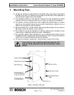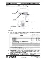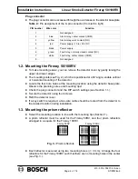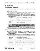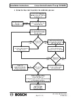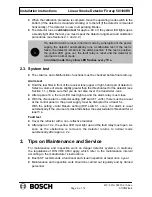
Installation Instructions
Linear Smoke Detector Fireray 50/100RV
ST/PMF/zab
610- F.01U.002.706 / A2.en
Page 5 of 14
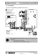
1.4. Connection
(if voltage drop
<
6 V)
(if voltage drop
>
6 V)
UEB
UEA
SB
SA
1
2
3
1
2
3
1
LSN
- U
+U
- U
+U
1
Bridges Br1, Br2 in position 2-3
F
AUL
T
ALARM
Power sup-
ply 10
-
30
V
Fireray 50/100 RV
rd
bl
R
E
NSB 100 LSN
I
3
I
4
NO
COM
NC
COM
NSB 100
EV 24 V - 24 V
I
1 NLT1
I
2
⊥
I
3 -U
Br 2
I
4 +U
II
1 NLT2
II
2
⊥
II
3 -U
II
4 +U
III
1
III
2
IV
1 RR
IV
2 R
V
1 KR
V
2 KA1
V
3 KA2
Br 1
VII
1
VII
2
VI
1
VI
2
ye
blk
gn
wh
2
2
Contacts in open position
Configuration for LSN:
Parameterize the NSB in the control
panel to control output
KA1-KA2/KR-R-RR and “Control with
Fireray”.
Operating mode switches:
Prism Targeting
Alignment Mode
Operating Mode
DIP switch:
Functions, see table 1. (page 3)
Output
for key switch
(optional)
Operating mode
switch
3K3
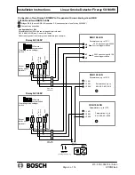
Connection of a Fireray 50/100RV using a NSB100 LSN at the fire panel
6 DA mini
distributor
on
off
-
+
DIP switch
(recommended set-
tings)
680
Ω
Select the following DIP switch settings for connection to a fire panel (see table
1. on page 3):
- «Alarm relay saves the alarm»
- «Fault relay at end of readjustment, no alarm».


