


Velocity controller integral time (in‐
tegral part)
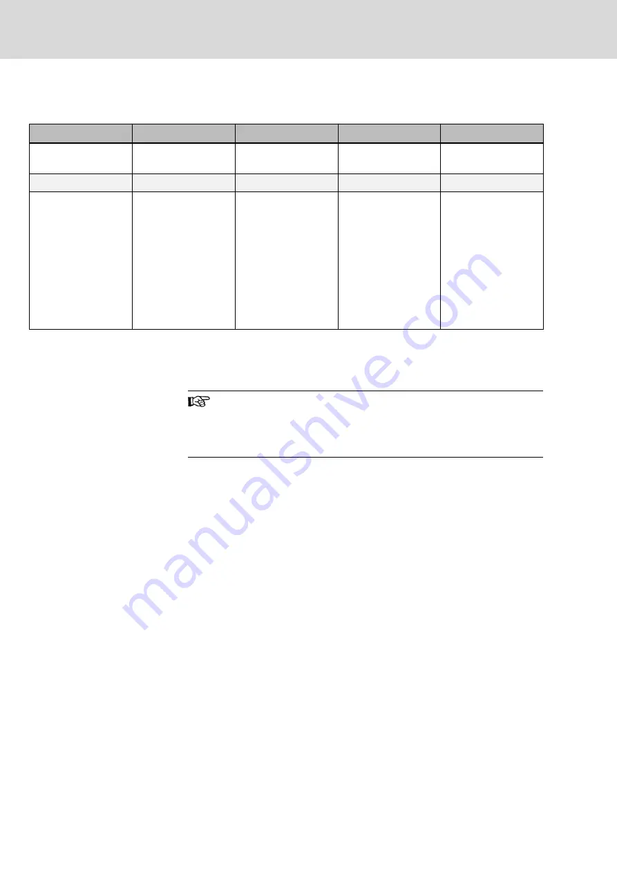
The following possibilities must be taken into account for the velocity control‐
ler integral time (integral part):
Possibility 1
Possibility 2
Possibility 3
Possibility 4
Alignment of length lin‐
ear scale and guides
ideal
not ideal
not ideal
not ideal
Integral Part
in both axes
in both axes
in one axis only
in no axis
Behaviour of the axes Since both motors fol‐
low the position com‐
mand value ideally,
there will not be a dis‐
tortion of the mechani‐
cal system
Both
axes
work
against each other un‐
til there is an equaliza‐
tion via the mechanical
coupling or until the
maximum current of
one or both drive con‐
troller(s) has been
reached and a control
effect is no longer pos‐
sible.
The axis without inte‐
gral-part permits a con‐
tinuous position offset.
The size of the position
offset depends on the
rigidity of the mechani‐
cal coupling of both ax‐
es and of the propor‐
tional gains in the posi‐
tion and velocity con‐
trol loop.
Both axes permit a
continuous position off‐
set. The size of the po‐
sition offset depends
on the proportional
gains in the position
and velocity control
loop.
Tab. 14-6:
Parameterization of the velocity controller integral time S-0-0101 for
Gantry-axes.
Optimization
The previously described procedure must be followed for optimizing the posi‐
tion and velocity loop.
Any parameter modifications that are made during the optimiza‐
tion of Gantry axes must always be made in both axes simultane‐
ously. If this is not possible, the parameter changes should be
made during optimization in smaller subsequent steps in both ax‐
es.
14.7.3
Estimating the moved mass using a velocity ramp
Often, the exact moving mass of the machine slide is not known. Determining
this mass can be made difficult by moving parts, additionally mounted parts,
etc.
The procedure explained below permits the moving axes mass to be estima‐
ted on the basis of a recorded velocity ramp. This permits, for example, the
acceleration capability of the axis to be estimated.
Preparation
This procedure requires the oscillographic recording of the following parame‐
ters:
●
S-0-0040, actual velocity value
●
S-0-0080, torque/force command value
You can either use an oscilloscope or the oscilloscope function of the drive in
conjunction with IndraWorks or NC.
Bosch Rexroth AG
DOK-MOTOR*-MCL********-PR05-EN-P
180/193
Rexroth IndraDyn L Ironless Linear Motors MCL
Commissioning, operation and maintenance
Summary of Contents for DOK-MOTOR-MCL Series
Page 14: ...Bosch Rexroth AG DOK MOTOR MCL PR05 EN P 12 193 Rexroth IndraDyn L Ironless Linear Motors MCL ...
Page 48: ...Bosch Rexroth AG DOK MOTOR MCL PR05 EN P 46 193 Rexroth IndraDyn L Ironless Linear Motors MCL ...
Page 64: ...Bosch Rexroth AG DOK MOTOR MCL PR05 EN P 62 193 Rexroth IndraDyn L Ironless Linear Motors MCL ...
Page 78: ...Bosch Rexroth AG DOK MOTOR MCL PR05 EN P 76 193 Rexroth IndraDyn L Ironless Linear Motors MCL ...
Page 84: ...Bosch Rexroth AG DOK MOTOR MCL PR05 EN P 82 193 Rexroth IndraDyn L Ironless Linear Motors MCL ...
Page 98: ...Bosch Rexroth AG DOK MOTOR MCL PR05 EN P 96 193 Rexroth IndraDyn L Ironless Linear Motors MCL ...


