background image

DSS User Interface

4–10

1070 066 028-101 (01.05) GB

4.5

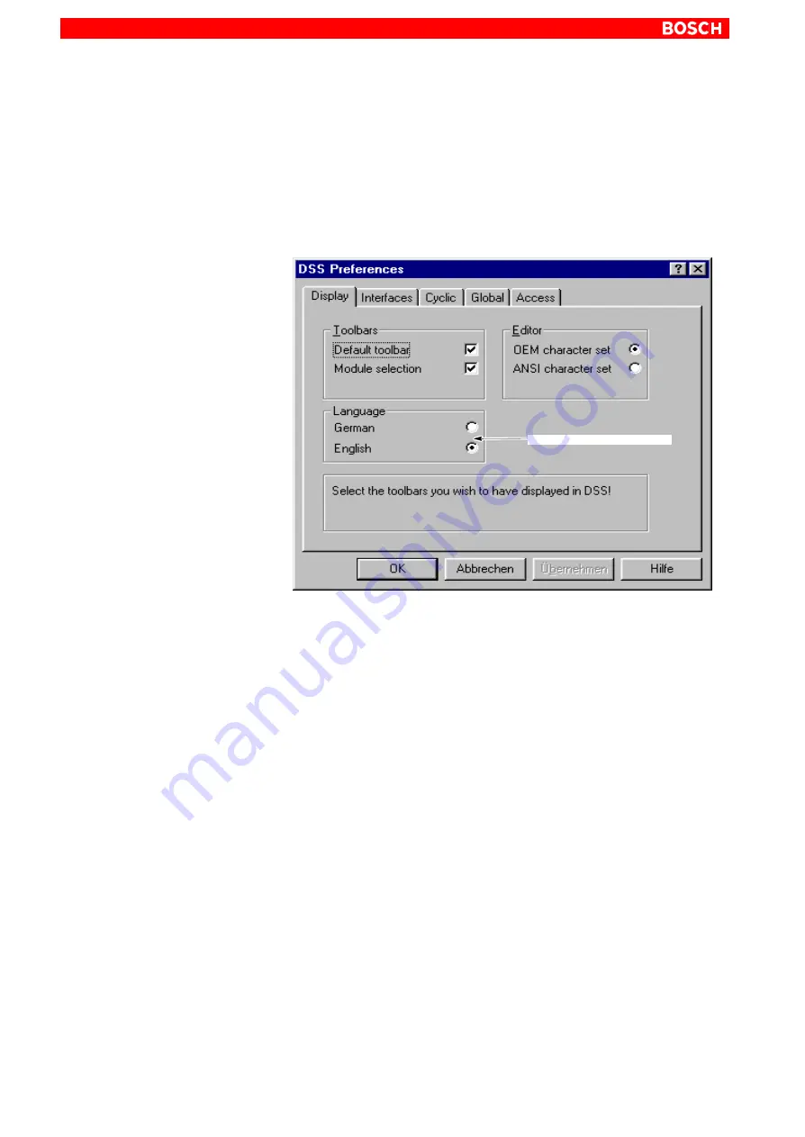
Selecting  the  language

The DSS user interface language may be changed over, but not the parame-
ter and status texts.

Language of user interface

L

Select: EXTRAS 

"

 PREFERENCES

Changing over the language

L

To activate the new language, you have to reboot.

Summary of Contents for DM**140D Series

Page 1: ...Antriebs und Steuerungstechnik Frequency Inverters DM 8001 ASM Parameter and Commissioning Manual Servodyn D 101 Edition ...

Page 2: ...mmissioning Manual 1070 066 028 101 01 05 GB E 2001 by Robert Bosch GmbH Erbach Germany All rights reserved including applications for protective rights Reproduction or distribution by any means subject to our prior written permission Discretionary charge DM 10 ...

Page 3: ... status display 4 9 4 5 Selecting the language 4 10 4 6 Save all parameter settings data backup 4 11 5 Commissioning 5 1 5 1 Parameters 5 2 5 1 1 Clock frequency 5 2 5 1 2 Output frequency 5 3 5 1 3 Data on the motor rating plate 5 4 5 1 4 V f characteristic 5 6 5 1 5 Setpoint ramps 5 8 5 1 6 Setpoint adjustment 5 10 5 1 7 Current limit 5 12 5 1 8 Emergency braking 5 13 5 1 9 Zero speed monitoring...

Page 4: ...ive 6 2 7 Firmware Update 7 1 7 1 Ensuring prerequisites 7 1 7 2 Selecting the download dialog 7 2 7 3 Selecting file to be downloaded 7 3 7 4 Starting the download 7 4 7 5 Restoring the drive data 7 5 8 Displays on the Module 8 1 8 1 Status warning displays 8 1 8 1 1 Fault messages 8 3 A Appendix A 1 A 1 Index A 1 ...

Page 5: ... Directive 73 23 EEC D the harmonized standards EN 50178 VDE 0160 and EN 60146 1 1 VDE 0558 11 D are designed for operation in industrial environments emission class A i e D no direct connection to public low voltage power supply D connection to the medium or high voltage system via a transformer In residential environments in trade and commerce as well as small en terprises class A equipment may ...

Page 6: ...lectronic equip ment Interventions in the hardware and software of our products unless de scribed otherwise in this manual are reserved to our specialized personnel Tampering with the hardware or software ignoring warning signs attached to the components or non compliance with the warning notes given in this manual may result in serious bodily injury or material damage Only electrotechnicians as r...

Page 7: ... 1 3 Safety markings on products Warning of dangerous electrical voltage Electrostatically sensitive components Warning of hazardous light emissions optical fibre cable emitters Lug for connecting PE conductor only Connection of shield conductor only ...

Page 8: ... in whole or in part may result in personal injury DANGER This symbol is used wherever insufficient or lacking compliance with in structions may result in personal injury CAUTION This symbol is used wherever insufficient or lacking compliance with in structions may result in damage to equipment or data files This symbol is used to draw the user s attention to special circumstances L This symbol is...

Page 9: ...y damage to equipment or environmental hazards Possible retrofits or modifications to the system using third party equipment therefore have to be approved by Bosch DANGER Health hazards through destroyed electrical components Do not destroy any built in components Dispose of destroyed com ponents in a proper manner DANGER Please note your local system specific regulations and require ments as well...

Page 10: ... and com ponents sensitive to electrostatic discharge ESD D Personnel responsible for storage transport and handling must have training in ESD protection D ESD sensitive components must be stored and transported in the pre scribed protective packaging D ESD sensitive components may only be handled at special ESD work places D Personnel working surfaces as well as all equipment and tools which may ...

Page 11: ...ing manual 1070 066 011 1070 066 031 1070 066 051 Servodyn D with analog interface Commissioning manual 1070 066 014 1070 066 034 Servodyn D with CANrho interface Commissioning manual 1070 066 017 1070 066 037 Servodyn D with motion control Commissioning manual 1070 066 015 1070 066 035 Frequency inverters DM 8001 ASM Parameter and commissioning manual 1070 066 008 1070 066 028 1070 066 053 Diagno...

Page 12: ...arks All trademarks of software installed on Bosch products upon delivery are the property of the respective manufacturer Upon delivery all installed software is copyright protected The software may only be reproduced with the approval of Bosch or in accordance with the license agreement of the respective manufacturer MS DOSr and Windowst are registered trademarks of Microsoft Corpora tion ...

Page 13: ...y trained technical personnel D In the case of multi axis systems you should always commis sion a single drive at a time D The motor must be properly fastened or flanged If this is not yet possible you must fix the motor e g with the help of suit able screw clamps so as to ensure that it cannot move even with maximum acceleration of the motor shaft Our service department will in any case be availa...

Page 14: ...e inverters Power supply L Turn the 24 V supply on Measure the voltage of the 24V supply at the con nector It must be between 20 8 28 8 V L Turn the power supply on and measure the voltage It must be between 360 506 V L Turn the power supply and the 24 V supply off Do not proceed unless all connectors terminals are de energized L Plug in all connectors terminals at the inverters Check connectors f...

Page 15: ...iagnostics and Service System Using this operator interface every inverter can be optimized and commissioned for the specific motor and the machine environment It also serves to call up a large number of status information H1 H3 7 segment display for status and error messages and parameters FG Green LED for external enable FGI Green LED for internal enable X 8 FG FGI 1 0 X 8 2 0 H 1 H 2 H 3 R D TE...

Page 16: ...ves to change the range or values in ascending order within a display level D Single steps in jogging operation D At increasing speed if the key is constantly depressed D Some modifications in single steps while the inverter is running in order to avoid dangers The Down key serves to change the range or values in descending order within a display level D Single steps in jogging operation D At incr...

Page 17: ...lay Computer booted temperature display status display see Section 2 1 Depress D key Select display functions Operating data A or parameter list PL1 PL8 Depress D key Select element Select the desired display from the A00 A15 area using the or keys Depress D key Return to previous level with Return keys Read current values ...

Page 18: ...ress D key Select parameter Select the desired parameter from the P00 P49 area using the or keys Depress D key Save new value entries with the D key when returning all unassigned decimal points of the display are flash ing Then return with the Return keys Before values can be changed the write protection must be disabled by pressing the boot key cf page 5 1 Change value The display shows the value...

Page 19: ...t permit inductive or capacitive coupling with live components If communication faults still occur an annular core on the connection lead may be helpful Use the folding ferrite coil part no 1070 918 766 L Connect X99 to COM1 or COM2 of your PC L Write down the port you used COM1 or COM2 Cannon connector 9 pole Type RS 232 Cable length max 15 m Cable type screened min core cross section 0 14 mm2 Tr...

Page 20: ... clicking on the command button INTERFACE SELECT in the DSS basic image L in the Primary connection field 1 V 24 connection ASM L Set the data in the Interface Preferences field 2 through the following dia log Click on OK to return to the Establish connection dialog L Clicking on OK in this dialog will cause the DSS to try to establish the de sired connection D In the event of a fault the Status f...

Page 21: ...the keyboard on the currently connected inverter you then have to re initialize the DSS This is the only way to ensure that the DSS does not work with invalid or outdated data CAUTION Uncontrolled motor movements are possible For as long as the drive is enabled you must neither press the RESET key nor disconnect the cable between the DSS and the drive First stop the movement and disable the drive ...

Page 22: ...its the program 2 Changes a DSS specific window Please note that iconized window symbols may be covered by open win dows Covered windows can be displayed by selecting the Windows menu Icon bar The meaning of the command buttons is also displayed when the mouse pointer is on the command button Symbols for axis selection without function in this figure Invokes the Overview window Starts the DSS moni...

Page 23: ...command button Command buttons and available functions Selecting command buttons that have several functions will open up a pull up menu Monitor edit parameter directly DSS file edit parameter file Increment initialization phase not applicable in this case Decrement initialization phase not applicable in this case Select interface DSS Home position Clear module error not applicable in this case Lo...

Page 24: ... on the command button Current parameter Current parameter value Read current pa rameter from the drive Transfer current pa rameters to the drive Parameter changes become immediately active Read all parame ters from the drive and save as asd file Read all parameters from an asd file and show them in a list Single parameter 1 Click on the Ident No field 2 Enter the parameter number to be edited Str...

Page 25: ...ll immediately take effect in the drive and will remain stored until the next change Even though only some parameters have been changed all parameters in all parameter lists will be replaced During the write process the 7 segment display on the inverter shows serial transmission Parameter list L In order to display a list of all parameters available in the frequency inverter first enter any desire...

Page 26: ... pa rameters to the drive Parameters become immedi ately active 1 To edit the parameters double click on the desired parameter in the list It will then be read again from the drive and written to the upper fields as current value Double clicking in step 1 has the same function as selecting the pa rameter and clicking on the Get command button To read all parameters in the list again mark the All I...

Page 27: ...nformation on D Current BTB1 warning diagnostics message in plain text D actual values of max 12 parameters D Last error after BTB2 was switched off L Select the menu sequence D DIAGNOSES MODULE STATUS DISPLAY Drive warning in plain text Display of max 12 actual values Last error after BTB2 was switched off ...

Page 28: ... 4 5 Selecting the language The DSS user interface language may be changed over but not the parame ter and status texts Language of user interface L Select EXTRAS PREFERENCES Changing over the language L To activate the new language you have to reboot ...

Page 29: ...ameter loss a firmware update or hardware replacement D document all parameters used for a drive L Make sure that no drive enable command has been given L Select the menu sequence FILE IDN BACKUP Enter a new file name The drive reads all parameters from all parameter lists and saves them in the previously specified file L Create a suitable directory structure on the hard disk drive of your PC to w...

Page 30: ...DSS User Interface 4 12 1070 066 028 101 01 05 GB Notes ...

Page 31: ...ey in the housing recess below the two LEDs with a pointed object For this pur pose carefully press down the signal cross link X810 which covers the but ton FG FGI H 3 8 1 0 X Boot button Since the boot button is hidden in normal operation the parameters are pro tected against unauthorized tampering The following general rules apply to programming the frequency in verter with the DSS D All values ...

Page 32: ...equency 2 0 9 0 kHz smallest step Range Hz factory setting all DMs DS 0 1 min max limits 9 x fmax P02 Please note the following dependencies Low clock frequencies High clock frequencies low motor noise low heat loss of the motor high module utilization see next page high output frequencies The clock frequency must be 9 x fmax Clock frequency kHz 2 4 6 8 10 200 400 600 800 1000 max output frequency...

Page 33: ... 5 up to 500 E0 6 0 6 up to 600 E0 7 0 7 up to 700 E0 8 0 8 up to 800 E0 9 0 9 up to 900 E1 0 1 0 up to 1000 Hz P02 A 0 0002 Maximum output frequency Selection of the precise maximum admissible output frequency 50 999 Hz smallest step Range Hz factory setting all DMs DS 150 0 1 1 100 limits P01 min max fclock 9 P03 A 0 0003 Minimum output frequency Selection of the lowest admissible output frequen...

Page 34: ... DM DS 45K A 4 7 0 5 47 7 A DM 85B 9 5 0 5 95 4 A DM140D 12 7 0 5 127 A factory setting DANGER Zero speed monitoring and the motor protection function are subject to the rated motor current Please make sure that the data has been entered correctly P05 A 0 0005 Rated motor power PN min Range kW max DM 4K 0 2 0 1 5 0 kW DM 8K 0 2 0 1 5 0 kW DM DS 15K 0 3 0 1 8 3 kW DM 30K A 0 7 0 1 16 6 kW DM DS 45K...

Page 35: ... voltage VN corresponds to the maximum output voltage Vmax rms of the inverter The output voltage cannot exceed the line voltage 150 460 V smallest step 1 Range V factory setting all DMs DS 380 min max P07 A 0 0007 Rated motor frequency fN 0 0 999 Hz smallest step Range Hz factory setting all DMs DS 50 0 1 1 100 limits P10 P02 min max ...

Page 36: ...tion processes of other axes connected to the link Thus the motor power is optimally used D In the case of linear type characteristics with torque boost the motor shows an improved starting behavior The output voltage is raised depending on the motor load D Using the I x R compensation the starting behavior of the motor is further improved if the torque boost is insufficient or has not been activa...

Page 37: ...quare law VF3 3 VF4 4 linear I x R with accel VF3 with torque boost P09 A 0 0009 I x R compensation 0 0 25 0 smallest step Range VN factory setting all DMs DS 0 1 min max P10 A 0 0010 I x R motor starting cut out frequency The I x R compensation is effective until the motor starting cut out frequency is reached 0 0 999 Hz smallest step Range Hz factory setting all DMs DS 0 1 1 100 limits P07 min m...

Page 38: ...resulting 2 step acceleration ramp P11 A 0 0011 Acceleration ramp D Simple acceleration ramp Acceleration from zero to the maximum output frequency P02 D 2 step acceleration ramp Acceleration time above the frequency break point P48 cf figure 0 1 999 sec smallest step Range sec factory setting all DMs DS 0 1 min max 10 P48 A 0 0048 Frequency break point 2 step acceleration ramp 0 999 Hz smallest s...

Page 39: ...max 10 P12 A 0 0012 Braking ramp The braking time to be adjusted refers to braking from the maximum output frequency P02 to f 0 0 1 999 sec smallest step Range sec factory setting all DMs DS 0 1 min max 20 CAUTION The selected braking and acceleration time values become longer if the inverter has reached the current limit P17 P18 This is to prevent further current increase ...

Page 40: ...f the following possibilities the external enable signal FG must be deactivated factory setting all DMs DS EF1 1 EF2 2 EF3 3 analog tsm 3 5 ms P14 ccw rotation P14 cw rotation EF4 4 EF5 5 EF6 6 EF7 7 EF8 8 EF9 9 analog tsm 6 5 ms analog tsm 12 5 ms analog tsm 25 ms analog tsm 50 ms analog tsm 100 ms analog tsm 200 ms analog 5 13 VDC at X23 5 6 or 0 20 mA at X23 5 7 X23 5 6 bridged P14 A 0 0014 Key...

Page 41: ...on D Do not activate enable signal D Enter the analog value of the maximum output frequency at the set point connector D Select P15 D Select Eu1 using the or keys When adjustment is done the display returns to Eu0 D Store the fmax adjustment by depressing the D key Another adjustment may be carried out P16 A 0 0016 f 0 adjustment offset adjustment all DMs DS Eo0 0 Eo1 1 normal display short time d...

Page 42: ...x DM 4K 0 9 0 1 9 5 A DM 8K 0 9 0 1 9 5 A DM DS 15K 1 5 0 5 15 9 A DM 30K A 3 1 0 5 31 8 A DM DS 45K A 4 7 0 5 47 7 A DM 85B 9 5 0 5 95 4 A DM140D 12 7 0 5 127 A factory setting P18 A 0 0018 Imax reduction with Ired signal Limitation with 24V signal at terminal strip X13 4 IRED min Range A max DM 4K 0 9 0 1 9 5 A DM 8K 0 9 0 1 9 5 A DM DS 15K 1 5 0 5 15 9 A DM 30K A 3 1 0 5 31 8 A DM DS 45K A 4 7 ...

Page 43: ...king 5 1 9 Zero speed monitoring With the help of the zero speed monitoring function the frequency inverter detects that the motor has stopped even without an additional motor en coder For further information see Section 5 2 2 P20 A 0 0020 Zero speed monitoring factory setting all DMs DS bu0 0 bu1 1 off on The display flashes and bu1 cannot be turned on if the FG enable sig nal had previously been...

Page 44: ...rect current braking may overheat the motor The electronic bimetal function P43 P45 protects the motor P21 A 0 0021 Activation of the direct current brake FG active DC braking if fact 0 or with DCB signal if fact fstart P24 DC braking only with DCB signal if fact fstart P24 deactivate FG all DMs DS dc0 0 dc1 1 off on on without fact 0 braking dc2 2 DC braking if P19 br1 if fact fstart P24 for P23 ...

Page 45: ... 0 5 11 2 A DM 30K A 3 1 0 5 22 5 A DM DS 45K A 4 7 0 5 33 8 A DM 85B 9 5 0 5 67 7 A DM140D 12 7 0 5 90 3 A factory setting P23 A 0 0023 Braking stopping time The braking stopping time refers to DC braking when the enable signal has been deactivated see page 5 14 0 1 999 sec smallest step Range sec factory setting all DMs DS 0 1 1 100 min max P24 A 0 0024 Direct current brake starting frequency fs...

Page 46: ...red ranges must be entered in order to be able to pass these ranges as fast as possible using the selected acceleration and braking ramps The fmax and f 0 limit values are used by the drive even if they are within the suppressed range P25 A 0 0025 Activate resonant frequency suppression factory setting all DMs DS Er0 0 Er1 1 off on P26 A 0 0026 Center frequency 1 0 0 999 Hz smallest step Range Hz ...

Page 47: ...60 fN p sN 1 nN p 60 fN sN rated motor slip nN rated speed min 1 n0 no load speed min 1 fN rated motor frequency Hz p number of pole pairs Optimize setting value The calculated setting value is falsified by slight deviations of the actual motor data from the rating plate data For very precise applications the setting value can therefore be corrected as follows after commissioning pursuant to Secti...

Page 48: ...odule peak current is determined This limit curve is designed to emulate the motor characteristic It can be determined e g by measuring the motor at different speeds on a test bench fmot Hz ftrans P34 fmax P02 I2max I1max Imax module a Asynchronous motors with field weakening fmot Hz ftrans fmax P34 P02 I2max 0 I1max Imax module b Asynchronous motors without field weakening I A I A P33 A 0 0033 Ac...

Page 49: ...12 7 0 5 127 A x P17 limits factory setting P36 A 0 0036 I2max current limit for fmax maximum frequency Final point of the speed dependent linear fall of the limit curve min Range A max DM 4K 0 9 0 1 9 5 A DM 8K 0 9 0 1 9 5 A DM DS 15K 1 5 0 5 15 9 A DM 30K A 3 1 0 5 31 8 A DM DS 45K A 4 7 0 5 47 7 A DM 85B 9 5 0 5 95 4 A DM140D 12 7 0 5 127 A x P17 limits factory setting Using the factory setting...

Page 50: ...for falling below this value D fact fset Monitors whether the actual output frequency fact matches the frequency setpoint fset for f 0 D n 0 When the external enable signal has been deactivated the inverter recognizes when the motor has reached n 0 min 1 and stops for approx 1 5 sec This output can only be selected if P20 bu1 For messages see Section 5 2 2 P38 A 0 0038 Reference frequency for fact...

Page 51: ...current rms AA1 A Standardization via P41 Active current rms AA2 A Reactive current rms AA3 A 0 9 15 9 5 1 5 25 15 9 3 1 50 31 8 4 7 75 47 7 9 5 150 95 4 12 7 200 127 Motor voltage AA4 V Link voltage AA5 V 1000 V Standardization via P42 Total power AA6 kVA Shaft output AA7 kW 0 4 7 5 7 5 0 7 12 5 12 5 1 5 25 25 2 3 37 5 37 5 4 6 75 75 6 2 100 100 Utilization AA8 200 Heat sink temperature AA9 _C 10...

Page 52: ... 25 0 A DM 30K A 3 1 31 8 0 5 50 0 A DM DS 45K A 4 7 47 7 0 5 75 0 A DM 85B 9 5 95 4 1 0 150 A DM140D 12 7 127 1 0 200 A x P17 limits factory setting P42 A 0 0042 Power standardization for total power AA6 and shaft output AA7 min Range kW max DM 4K 0 4 0 1 7 5 kW DM 8K 0 4 0 1 7 5 kW DM DS 15K 0 7 0 1 12 5 kW DM 30K A 105 0 2 25 0 kW DM DS 45K A 2 3 0 5 37 5 kW DM 85B 4 6 0 5 75 0 kW DM140D 6 2 0 ...

Page 53: ...tallic relay the following parameters must be entered D Rated motor current P04 D Release current constant P44 D Release time P45 For safety reasons the last thermal load value of the motor remains stored when the inverter is switched off It will be taken as the initial value when switched on again When the inverter has been switched off it should be switched on again while the motor is cooling do...

Page 54: ...stant The value to be adjusted must be obtained from the motor manufacturer It is referred to speed independent ventilation bF1 characteristic 2 0 15 smallest step Range factory setting all DMs DS 0 1 min max 6 0 P45 A 0 0045 Release time 1 0 100 sec smallest step Range sec factory setting all DMs DS 0 1 min max 10 0 ...

Page 55: ...the un dervoltage limit If the line power returns during the braking phase the inverter accelerates in a controlled restart operation in accordance with the acceleration ramp setting D Braking with setpoint control The braking operation starts when the d c link voltage exceeds 700 V Depending on the external moment of inertia the inverter extends the braking ramp selected in P12 and maintains the ...

Page 56: ...ecific needs are deleted CAUTION Loss of data The optimization data of the current parameter list get lost when se lecting Default setting P46 A 0 0046 Load default setting The default setting is only loaded into the selected parameter list all DMs DS LP0 0 LP1 1 normal display default setting mains off on automatic return For loading the default setting 1 Select LP1 existing values still remain a...

Page 57: ...um value Check the maximum admissible speed for clockwise and counter clockwise rotation The direction of rotation is changed by reversing the polarity of the setpoint cables connected to X6 5 and X6 6 5 2 1 Subsequent optimization during operation During operation the drive behavior can be further improved When the enable signal FG has been activated the following parameters can be subsequently o...

Page 58: ... control activate parameter P20 If the FG enable signal had been activated before first cycle power to the unit then activate P20 DANGER Zero speed control is guaranteed only if the motor is standing when monitoring is switched on The following messages are output in connection with zero speed control on Messages FGI relay X34 3 n 0 running or standing operation 0 V decelerating 24 V 0 V standing ...

Page 59: ...is thereby exceeded the messages limit current Ilimit overcurrent F22 or driver fault F20 may be signaled Adjustments The following settings must be checked D I x R compensation P09 P10 Overexcitation or underexcitation of the motors during operation should be avoided D acceleration and braking times P11 P48 P49 P12 D direct current brake P21 P24 A test should be carried out whether DC braking mak...

Page 60: ...Commissioning 5 30 1070 066 028 101 01 05 GB Notes ...

Page 61: ...in the parameter file Please observe the syn tax requirements when making changes L Make sure that all of the hardware checks described in section 2 have been properly carried out 6 1 Edit and load asd file The asd file can only be opened in the main menu in order to be edited with a file editor 1 Select menu sequence FILE OPEN ASM FILE The editor is started by hitting OK in the Open dialog Change...

Page 62: ...as not disabled by pressing the boot button cf page 5 1 4 Click on the Set command button cf figure above During the write process the 7 segment display on the inverter shows serial transmission L Close the editor L If necessary perform a setpoint calibration see page 5 11 6 2 Couple next drive L Remove the connection line from X99 and plug it to X99 of the next module to be commissioned L Initial...

Page 63: ... description 7 1 Ensuring prerequisites L Link the drive in question to the PC and establish communication between the drive and the DSS Please note the information provided in section 4 1 L Make sure that a data medium containing the new firmware is available The label will contain the release number and date of the firmware L Make a safety backup of the original data In the course of the update ...

Page 64: ...p to Bosch Service Level 2 Select the menu sequence EXTRAS DSS PREFERENCES ACCESS Cancel Help Apply The user group is changed by hitting OK as soon as the relevant pass word has been entered You may obtain the password on request from Bosch Automationstech nik Erbach D Tel 49 0 6062 78 0 D Email AT Support Drives bosch com ...

Page 65: ...ission 7 3 Selecting file to be downloaded L Proceed as follows 1 Insert the floppy disk containing the new firmware into the PC s drive A 2 Click on Browse command button cf Figure above The Open dialog is displayed 1 2 Cancel Network Folder Filename File Type Drives Read Only Open 3 Click on 1 and select drive a 4 Click on the asmd_xxx hex file in the area 2 The DSS will now dis play the name of...

Page 66: ...knowledge the error messages by hitting Ok The system will open an information dialog in which you are requested to RESET the drive and call up the Init module type function Follow the instructions displayed and then confirm the information dialog by hitting Ok Repeat this procedure from point 1 If no communication can be established even after several at tempts reduce the data transmission speed ...

Page 67: ...the operating system The screen shows the DSS basic image 2 Select the following menu from the DSS basic image CONTROL DSS RESET 3 Restore the required parameter settings from your backup file to the drive This process has been described in connection with series commission ing in section 6 1 The firmware update has now been completed ...

Page 68: ...Firmware Update 7 6 1070 066 028 101 01 05 GB Notes ...

Page 69: ...ck frequency or load D Select motor with higher rating D Verify bimetal setting More operating data can be read from the 7 segment display For operation refer to section 3 3 Read from DSS Unit Description A00 A 0 1000 Hz Actual output frequency fact Current motor frequency A01 A 0 1001 Hz Setpoint output frequency fset Specified output frequency A02 A 0 1002 A Total current rms value of the total ...

Page 70: ...ve current limit is adjusted depending on the selected settings and the current heat sink temperature A12 A 0 1012 TEMP warning WARNING after deactivation of TEMP relay U00 no warning U01 heat sink temperature too high U02 motor temperature too high Only if bimetal function P43 P45 is active U03 heat sink and motor temperature too high A13 A 0 1013 Last fault after STA deactivation After restart t...

Page 71: ...D Check output stage Overcurrent Admissible module peak current exceeded for 2 sec D Reduce load D Flatten braking acceleration ramps D Check application Overvoltage in link Ulnk 860 V unless F20 D Check mains voltage D Reduce braking power Motor connection Motor not properly connected D Check motor connection Heat sink overtemperature D Check air supply D Check fan Motor overtemperature Electroni...

Page 72: ...B Displays in vertical ar rangement on the module Measures Fault Drive was switched off Error in RAM memory D Replace module EEPROM error EEPROM cannot be read written D Replace module to Real time error Processor error D Restart module D Replace module ...

Page 73: ...stablish connection 4 2 Exit the DSS program 4 4 F Fault messages 8 3 8 4 FEPROM Backup 4 11 Firmware update 7 1 Floppy disk drive 1 7 G Grounding bracelet 1 6 H Hard disk drive 1 7 I I x R compensation 5 6 IDN backup 4 11 Initializing DSS 4 3 Intended use 1 1 Interface disconnect connection cable 4 3 setting parameters 4 1 X99 4 1 K Keypad 3 2 L Low Voltage Directive 1 1 M Machinery directive 1 1...

Page 74: ...es commissioning 6 1 load files 6 1 Setpoint 5 10 Setpoint ramps 5 8 Shaft output 5 21 Slip compensation 5 17 Spare parts 1 6 Stalling warning 5 18 Status displays 8 1 T Temperature sensor 5 23 Torque boost 5 6 Trademarks 1 8 U User group change 7 2 Utilization 5 21 W Warning displays 8 1 Write protection disabling 5 1 Z Zero speed monitoring 5 13 Zero speed control 5 28 ...

Page 75: ...t Bosch GmbH Geschäftsbereich Automationstechnik Schraub und Einpress Systeme Postfach 11 61 D 71534 Murrhardt Fax 0 71 92 22 1 81 Robert Bosch GmbH Geschäftsbereich Automationstechnik Entgrattechnik Postfach 30 02 07 D 70442 Stuttgart Fax 07 11 8 11 3 34 75 Robert Bosch GmbH Geschäftsbereich Automationstechnik didactic Berliner Straße 25 D 64701 Erbach Fax 0 60 62 78 8 33 Robert Bosch GmbH Geschä...

Reviews: