INSTALLATION MANUAL
TOW ASSIST ABS & SWAY MITIGATION SYSTEM
www.dexteraxle.com
Page 1: ...INSTALLATION MANUAL TOW ASSIST ABS SWAY MITIGATION SYSTEM www dexteraxle com ...
Page 2: ...is is the safety alert symbol It is used to alert you to potential injury hazards Obey all safety messages that follow this symbol to avoid possible injury or death The purpose of this document is to detail the installation requirements and guidelines for the Tow Assist Detail within this document is provided by Dexter as a guideline to the proper and correct installation for trailer manufacturers...
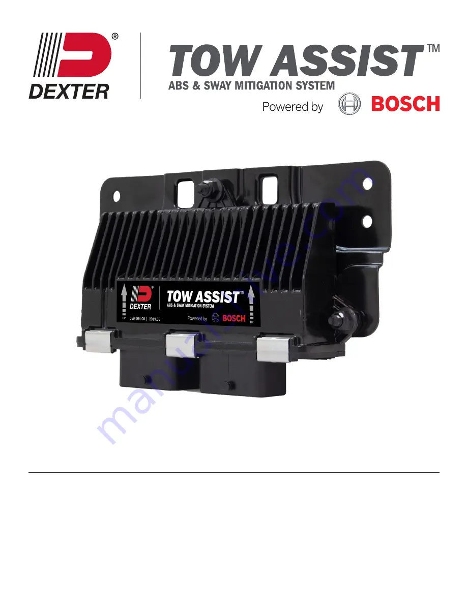
Page 3: ...EM ABS SWAY MITIGATION SYSTEM ABS SWAY MITIGATION SYSTEM TOW ASSIST ABS SWAY MITIGATION SYSTEM Poweredby UP UP Trailer Requirements Wheel Speed Sensor Availability The trailer to which Tow Assist is to be fitted must have axles equipped with Tow Assist brakes and hub drums Wheel speed sensors are designed into the Tow Assist brake and are an integral part of the system Chassis Rail Mounting Suitab...
Page 4: ...he Universal Mounting Bracket is parallel to the chassis or carrying surface of the unit When mounted on a finished unit this should place the X and Y axis no more than 5 from parallel to the ground NOTE THE Universal Mounting Bracket SHOULD NOT CONTACT THE FLOOR Allowance of 1 8 air gap is appropriate to avoid transmission of unwanted vibration The mounting location should allow for proper cleara...
Page 5: ...ns are valid for the Tow Assist system Single Axle Trailer A single front axle FL FR should be selected during trailer variant configuration Tandem Axle Trailer all axles braked Both braked axles Front Rear FL FR RL RR are selected and controlled by Tow Assist Triple Axle Trailer all axles braked All braked axles Front Center Rear FL FR CL CR RL RR are selected and controlled by Tow Assist Wheel S...
Page 6: ...ake Magnet Signal 1 6 ECU Connector Brake Magnet 1 6 Common Ground Point ECU Ground ECU Connector Common Ground Point Brake Magnet Signal 1 6 Brake Magnet 1 6 Common Ground Point Trailer Supply Ground Trailer Power Supply on board battery or tow vehicle power Common Ground Point Wire Harness Diagram with Breakaway Only ECU not powered during breakaway feed through braking Junction Box Red Battery ...
Page 7: ... power harness and the axle harness This clamp will rigidly fix the cable assemblies for vibration resistance CAUTION Improperly mounting the cable clamp will result in vibration and damage to the product Route the harness as desired avoiding tight bends and excessively sharp edges locating the power wires light harness and OBD2 extension Route it through the cable clamp at the ECU Utilize cable c...
Page 8: ...acking plate Plug in magnet connector to provided connector on backing plate Repeat for each wheel end Ensure axle harness cable routes through the cable clamp adjacent to the ECU that has the power harness Insert the PLUG A connector to the right side PLUG A receptacle and secure the connector latch The latch locks on a feature on the wire retention cap as identified Make sure there is no orange ...
Page 9: ... to the Blue brake wire and the Tow Assist will be ready to drive and the indicator light will be green The brake signal could be a momentary 12v application to the blue wire or a valid signal from a brake controller Valid Brake Signal from Brake Controller Brake controllers available will vary somewhat on the exact signal produced at standstill Tow Assist requires a signal that exceeds a threshol...
Page 10: ...on selections have been made click the Save Config button Type in the desired file name and hit save File type must remain as cfg 5 The current data on the screen after the config file was saved can still be edited and saved under another name if needed Reload the config file or restart the program to force data to be not editable on screen Configuration from Saved File After parameter file has be...
Page 11: ...ssist system will flash both colors on the Indicator light while the PC is talking to Tow Assist ECU The data in blue appears showing the current data in the ECU This typically will be empty with new out of the box ECUs The Program Config button is highlighted ready to write data to ECU User hits Enter key to configure ECU 6 User hits Enter key to confirm Flashing configuring writing ECU When the ...
Page 12: ...he system should power up as described in Tow Assist Power Up section The indicator light will not be on for either color at the end of a successful startup 3 Apply tow vehicle power to the brake request wire momentarily simulate a brake application by the tow vehicle The magnets will pull in during power application and the indicator light should light green indicating the ECU has entered drive m...
Page 13: ...TIGATION SYSTEM ECU Indicator Light Power Indicator Light Harness OBD2 Connector Yellow Left Side Indicator WSS Connector Magnet Connector External Load Connector Front Axle Rear Axle Reference Figure 3 Example of Tandem Axle Harness and 30 Power Harness ...
Page 14: ...hin the applicable warranty period of such defect and provide us with the axle or applicable component serial number and any substantiation of such defect which may include but is not limited to the return of part s that we may reasonably request 3 The axles suspensions and components must have been installed and maintained in accordance with good industry practice and any specific Dexter recommen...
Page 15: ...sure this template is printed to scale and the holes line up to the ECU before drilling into trailer NOTE THE Universal Mounting Bracket SHOULD NOT CONTACT THE FLOOR Allowance of 1 8 air gap is appropriate to avoid unwanted vibration and damage to the ECU 125 MIN FLOOR OF TRAILER 787 7 165 187 4X ...
Page 16: ...2900 Industrial Parkway East Elkhart IN 46516 Phone 574 295 7888 Fax 574 295 8666 www dexteraxle com ISO 9001 2015 Certified 2021 01 2021 Dexter Axle Company LIT 020 00 ...