DICENTIS
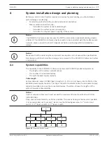
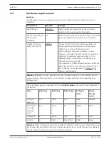
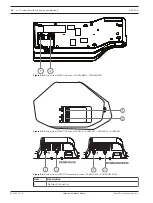
System installation design and planning | en
29
Bosch Security Systems B.V.
Hardware Installation Manual
2021.01 | V2.2 |
4.4.1
Redundant cabling for DCNM-APS2/DCNM-PS2 units
This section describes how to create redundant cabling for DCNM-APS2 / DCNM-PS2 type
units. The maximum number of Ethernet devices in the largest possible loop (including the
root switch) is 22. In a system with no Ethernet switch(es), the APS is the root switch.
The total number of devices allowed in a loop depends on:
–
The type of device connected in the loop (for example, DCNM-MMD2 devices consume
more power than DCNM-DE devices).
–
The length of the loop (cable also consumes power).
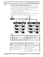
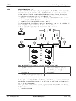
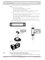
The figure shows how to calculate the number of devices in the loop. The grey line shows the
largest loop. The # sign shows the way the devices are counted.
In the example below up to 19 (22 - 3 = 19) discussion devices can be connected.
#1
1
2
Figure 4.7:
DICENTIS discussion devices connected with redundant cabling between DCNM-PS2 / DCNM-APS2
type units
1 DICENTIS system
2 Network switch (with optional
redundant power supply)
3 DCNM-APS2
4 DCNM-PS2
5 DICENTIS cabling (redundant loop)
Cabling possibilities (DCNM-APS2/DCNM-
PS2)
Limitations/requirements
Create a redundant loop by connecting the
DICENTIS devices in a daisy chain
configuration from a high power socket on a
DCNM-PS2 / DCNM-APS2 to a high power
socket on another DCNM-PS2.
The redundancy is for power and control. If
the DCNM-APS2 fails, the devices remain
connected, but audio is lost.
To enable redundancy:
–
Rapid Spanning Tree Protocol (RSTP)
must be enabled in the DICENTIS
Conference System.
Summary of Contents for DCNM-APS2
Page 1: ...DICENTIS Conference System en Hardware Installation Manual ...
Page 2: ......
Page 79: ......


