


1 689 975 197 (2006-09-22)
Robert Bosch GmbH
en
4
ACS 500
9.10 Replacing force sensors for used oil, fresh oil
and UV contrast medium scales
This section describes the replacement of the force
sensor for the fresh oil scale. The replacement procedure
for the other two scales (used oil and UV contrast
medium) is the same. Ensure that the terminals are
correct when connecting the force sensors to the
control/display unit (see also section 12.1).
Procedure:
1. Turn off ACS 500 at master switch.
2. Remove mains connector.
3. Remove electronic compartment cover.
45
979
0-1
4
1
2
4
6
3
5
7
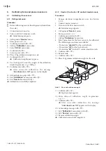
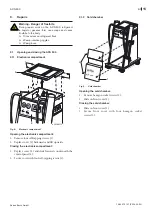
Fig. 27: Removal of force sensor
4. Remove tank (4).
5. Disconnect connecting lead from control/display unit.
6. Connect hose line (1).
7. Remove hexagon bolts (5).
8. Remove force sensor with pipe union from the retaining
plate (3).
9. Remove hexagon bolts (7) and remove retaining plate
(2) for pipe union from the force sensor.
i
459790-15
2
7
9
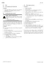
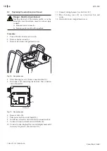
Fig. 28: Assembly of force sensor
10. Place new force sensor on the work surface with the
direction arrow (9) pointing upwards.
11. Place retaining plate (2) with pipe union onto the new
force sensor and secure with hexagon bolts (7).
45
979
0-1
6
5
3
1
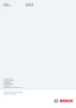
Fig. 29: Force sensor installation
12. Insert new force sensor in the retaining plate (3).
13. Secure force sensor with hexagon bolts (5).
14. Connect hose line (1 - See also section 11).
15. Connect connecting lead to control/display unit
(see section 12.1).
16. Attach electro
nic compartment cover.
17. Calibrate force sensor (see section 6.1.2).


