


F 002 DG9 448
2018-02-01
|
Bosch Limited
Product description | ACS 151 | 9
en
459897_238Nkv
1
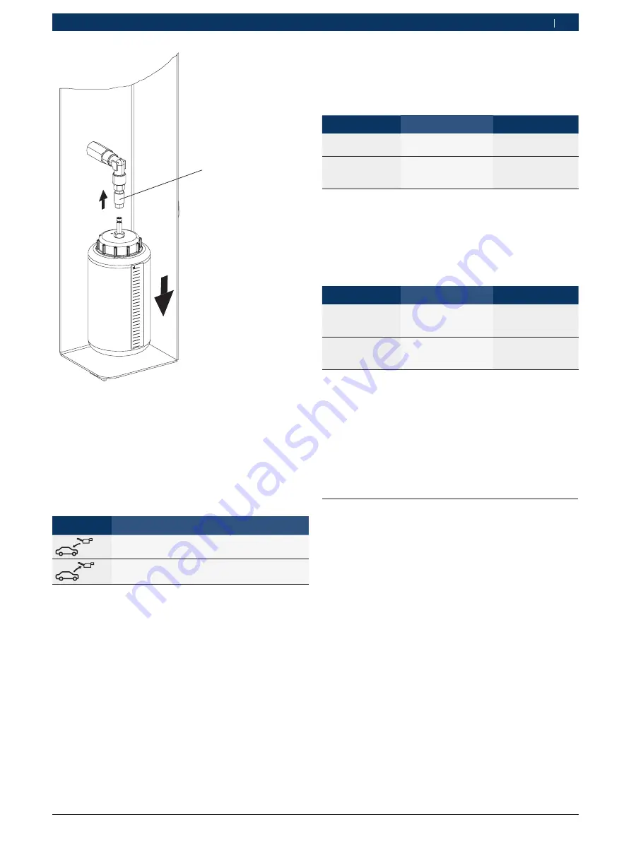
Fig. 4:
Detaching the used oil bottle
1 Connector
To detach the used oil bottle, pull the connector
(Fig. 4, Pos. 1) slightly upwards and pull down the
bottle.
Observe the symbols on the front panel to identify the
bottles. The following table lists the symbols and their
description.
Symbol
Description
Fresh oil bottle
Used oil bottle
3.3.3
Quick couplers
The quick couplers (see fig. 7) are connected to the
service connections on the vehicle A/C system to per-
form the service. To detach the quick couplers from
the service connection on the car A/C system, grip the
knurled portion of the coupler. Depress the coupler
slightly and pull back the knurled portion gently to re-
lease the coupler.
To attach the coupler to the service connection on the
on the car A/C system, place the coupler on the service
connection and pull back the knurled portion of the
coupler. Press gently.
3.3.4
Valves for charging oil
Fresh oil injection can be performed by turning the
valve above the oil bottle. Refer the following table for
more information.
Operation
Action
Trigger
Inject fresh oil
Turn valve anticlock-
wise
Software prompt
Stop fresh oil
injection
Turn valve clockwise
After required quan-
tity of fresh oil is
filled.
3.3.5
Valves for refrigerant recovery / recharge /
tank fill
Refrigerant recovery / recharge can be performed by
turning the valves above the respective hoses (HP / LP).
Refer the following table for more information.
Operation
Action
Trigger
Fill refrigerant /
recover
refrigerant
Turn red / blue knobs
anticlockwise
Software prompt
Stop filling /
recovering
refrigerant
Turn red / blue knobs
clockwise
Software prompt
3.3.6
Brakes
The ACS 151 can be prevented from rolling away by ap-
plying brakes on the front wheels.
3.3.7
Power cable and master switch
The power cable is connected to the inlet and then to
the mains supply. The ACS 151 can be powered on by
switching on the master switch.
3.4
Description of function
The functions performed by the ACS 151 are:
R
Recovery and recycling - Refrigerant is recovered
from the car A/C system. It is then recycled to
remove suspended particles and moisture. The
cleaned refrigerant is stored in the refrigerant tank.
R
Vacuuming and leak detection - A deep vacuum is
created and car A/C system is checked for leaks.
R
Recharging refrigerant - The refrigerant in the refrig-
erant tank is charged into the vehicle A/C system.
R
Replenishing vehicle compressor oil along with re-
frigerant as specified by the vehicle manufacturer


