
UPSaver
installation and start-up
OMH44149 REV. C
83
5.3 SHUT-DOWN
PROCEDURE
It is advisable to shut-down the
UPSaver
system by using the emergency power off push-
button (EPO) and then proceed to open the general switches OCB, SBCB, BCB and RCB.
Operating the EPO push-button allows the control logic to stop the system in a controlled
manner, so that whatever operation will follow, it will be done in complete safety.
In case the EPO push-button is not installed, or the operator needs to operate in a different
way, proceed as indicated below.
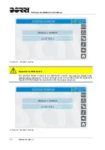
1)
Stop all power modules using, for each one of them, the procedure indicated at
paragraph 5.6.
2)
Open the general switch
OCB
.
3)
Open the general switch
BCB
.
4)
Open the general switch
RCB
.
5)
Open the general switch
SBCB
.
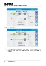
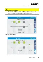
5.4 SWITCHING
PROCEDURE TO MANUAL BYPASS
The load is transferred to Manual Bypass with no interruption of supply to the loads. In this
configuration, the system can be restarted via the return procedure from load on manual
bypass, without the need to de-energize the loads.
Manual bypass
To perform the switching procedure correctly, make sure no alarms are present on
the system.
During Manual Bypass the load is supplied directly by the input mains, therefore
continuous supply cannot be guaranteed to the loads.
1) Move
the
Bypass_SW
selector to the
BYPASS
position.
2)
Close the switch MBCB.
3)
Stop all power modules using, for each one of them, the procedure indicated at
paragraph 5.6.
4)
Open the general switch
OCB
.
5)
Open the general switch
BCB
.
6)
Open the general switch
RCB
.
7)
Open the general switch
SBCB
.
Summary of Contents for UPSaver 1000 kVa
Page 2: ...UPS OPERATING MANUAL UPSaver 400 1600 kVA ...
Page 5: ......
Page 7: ...Warnings and general information 2 OMH44148 REV A ...
Page 13: ......
Page 20: ...UPSaver installation and start up OMH44149 REV C 7 ...
Page 33: ...UPSaver installation and start up 20 OMH44149 REV C Picture 6 Handling of the power module ...
Page 57: ...UPSaver installation and start up 44 OMH44149 REV C Picture 46 UPS cabinets upper fixing ...
Page 59: ...UPSaver installation and start up 46 OMH44149 REV C Picture 49 Power module cables terminals ...
Page 115: ...UPS user manual 6 OMH44150 REV B ...