
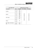


UPSaver
installation and start-up
74
OMH44149 REV. C
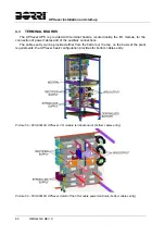
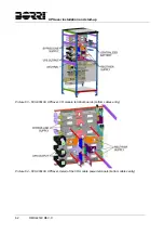
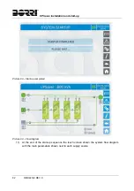
5.2 START-UP
PROCEDURE
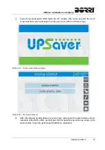
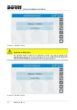
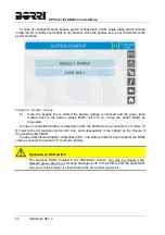
First system start-up
During the first start-up of the
UPSaver
system the I/O module and the power
modules are configured and the system redundancy is defined.
The first start-up is performed either by the manufacturer's technical personnel or
authorized service centres.
EPO push-button and phase rotation
Before switching the UPS on, make sure that:
1) the emergency power off “EPO” push-button, if installed, is not pressed. If not,
press it back to the rest position;
2) the input and output phase rotation is correct.
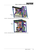
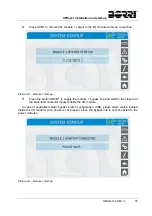
Circuit breaker BCB
In case of centralized battery configuration the switch
BCB
is installed externally to
the UPS system.
Do not close
the battery breaker BCB before it’s required by the front panel. Serious
damages to the UPS internal parts and/or to the battery may occur.
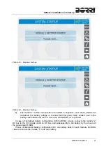
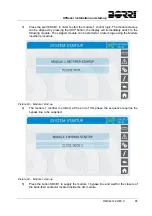
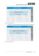
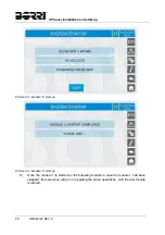
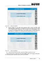
The
UPSaver
system start-up is completely guided; the indications available by the
touch
screen
allows the complete comprehension of the various steps and helps the operator in
performing the requested operations in the correct sequence.
However, all the sectioning devices must be mandatorily manoeuvred under the supervision
and control of engineers who are qualified to operate on electrical circuits.
Use qualified personnel only
Any electrical manoeuvre must be carried out by qualified and trained personnel.
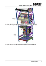
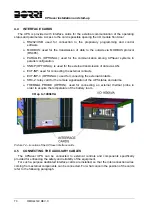
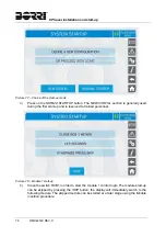
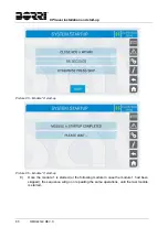
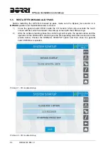
The system start-up is essentially split into three phases:
I/O module (
centralizer
) supply and control logic start-up;
power modules start-up by closing the switches located in the distribution column at
the sides of the I/O module;
Closure of the general switches inside the I/O module.
Summary of Contents for UPSaver 1000 kVa
Page 2: ...UPS OPERATING MANUAL UPSaver 400 1600 kVA ...
Page 5: ......
Page 7: ...Warnings and general information 2 OMH44148 REV A ...
Page 13: ......
Page 20: ...UPSaver installation and start up OMH44149 REV C 7 ...
Page 33: ...UPSaver installation and start up 20 OMH44149 REV C Picture 6 Handling of the power module ...
Page 57: ...UPSaver installation and start up 44 OMH44149 REV C Picture 46 UPS cabinets upper fixing ...
Page 59: ...UPSaver installation and start up 46 OMH44149 REV C Picture 49 Power module cables terminals ...
Page 115: ...UPS user manual 6 OMH44150 REV B ...