


UPSaver
installation and start-up
OMH44149 REV. C
59
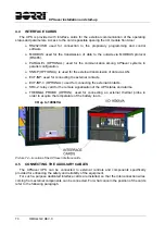
4.2
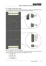
BACK-FEED PROTECTION DEVICE
The back-feed protection device is installed inside the I/O module on
UPSaver
systems with
distributed static bypass switch.
The device is a contactor for each power module, which automatically disconnects the
bypass line in case of failure of the static switch, in order to avoid voltage feed-back on the input
terminals during a mains failure.
The use of a device installed inside the UPS allows a higher flexibility of use, as only the
bypass line is cut leaving the rectifier battery charger in operation.
The use of an external device forces the user to separate the UPS supply lines (rectifier and
bypass) if the flexibility and availability of the UPS are supposed to be kept unaltered.
The
UPSaver
systems with centralized static bypass switch are provided with voltage-free
contacts which can be used to operate the shunt trip coil of the external sectioning device; the
external device is not part of the UPS supply and is provide and installed at customer care.
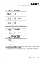
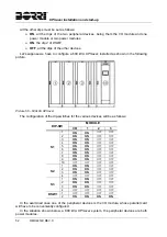
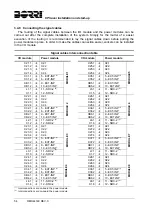
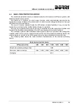
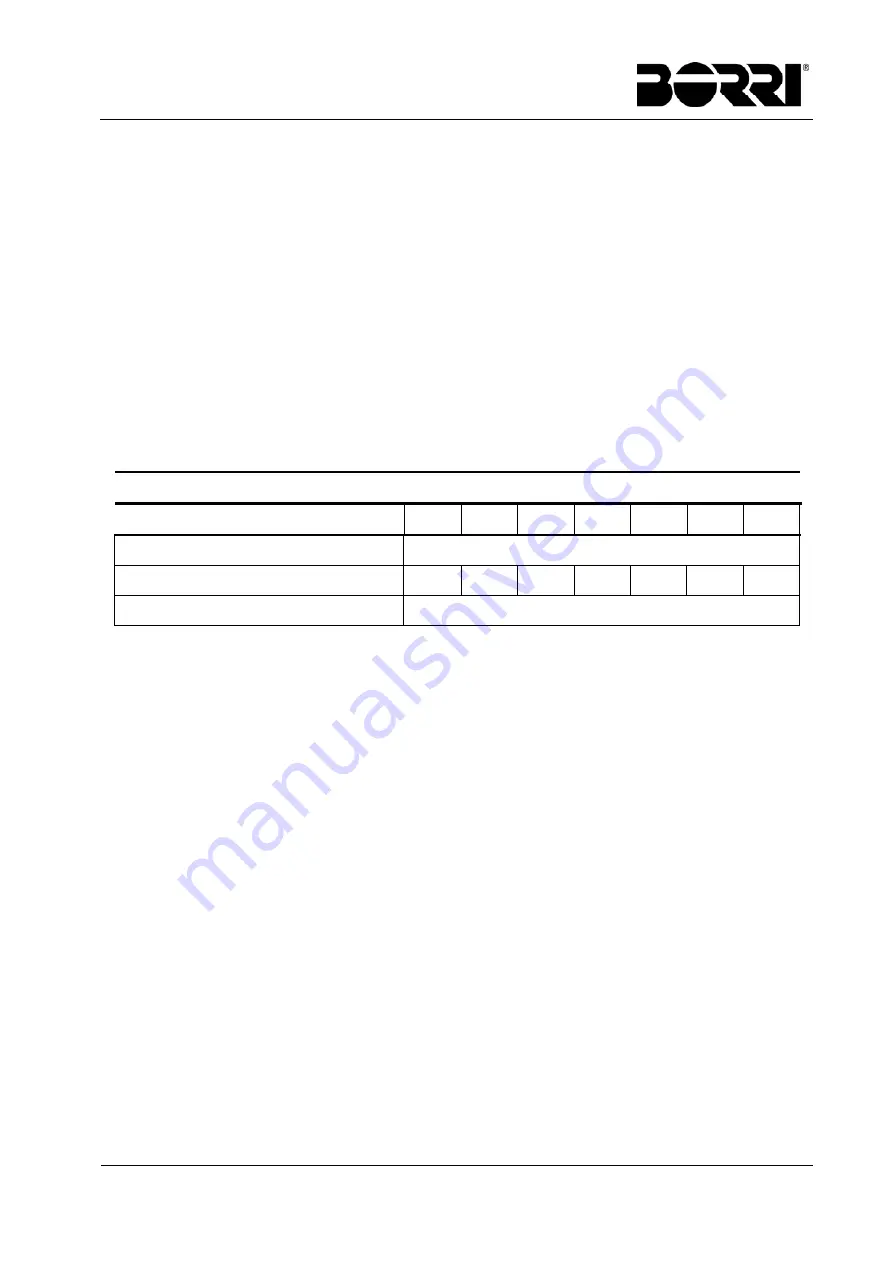
The following table shows the main electrical characteristics of the external sectioning
device.
Back-feed protection device
UPS power (kVA)
400 600 800 1000 1200 1400 1600
Maximum operating voltage (Vac)
690
Minimum rated current (A)
800
1250 1600 2000 2500 3200 3200
Category AC-1
Summary of Contents for UPSaver 1000 kVa
Page 2: ...UPS OPERATING MANUAL UPSaver 400 1600 kVA ...
Page 5: ......
Page 7: ...Warnings and general information 2 OMH44148 REV A ...
Page 13: ......
Page 20: ...UPSaver installation and start up OMH44149 REV C 7 ...
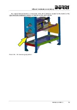
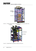
Page 33: ...UPSaver installation and start up 20 OMH44149 REV C Picture 6 Handling of the power module ...
Page 57: ...UPSaver installation and start up 44 OMH44149 REV C Picture 46 UPS cabinets upper fixing ...
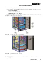
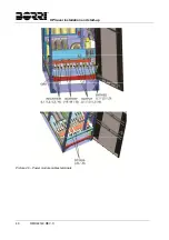
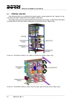
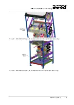
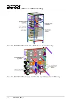
Page 59: ...UPSaver installation and start up 46 OMH44149 REV C Picture 49 Power module cables terminals ...
Page 115: ...UPS user manual 6 OMH44150 REV B ...