


UPSaver
installation and start-up
56
OMH44149 REV. C
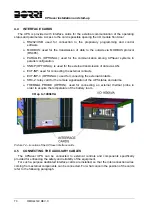
4 ELECTRICAL
CONNECTION
The electrical connection is part of the work which is normally provided by the company that
carries out the product installation. For this reason, the UPS manufacturer shall not be held
responsible for any damages due to wrong connections.
Use qualified personnel only
All the operations related to the electric connection must be carried out by qualified
and trained personnel.
Work in compliance with the local standards
The installation of
UPSaver
UPS must be carried out in compliance with national and
local regulations.
Connection of ground cable
The grounding of the UPS via the relevant terminal is mandatory. It is strongly
recommended to connect the ground terminal as first terminal.
The electrical connection is part of the work which is normally provided by the company that
carries out the electrical installation and not by the UPS manufacturer. For this reason, the
following recommendations are only an indication, as the UPS manufacturer is not responsible
for the electrical installation. In any case we recommend to carry out the installation and the
electrical input and output connections in compliance with the local standards.
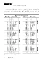
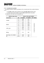
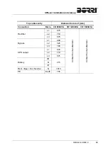
Cables must be selected bearing in mind technical, financial and safety aspects. The
selection and the sizing of cables from a technical viewpoint depend on the voltage, on the
current absorbed by the UPS, on the bypass line and on the batteries, on the ambient
temperature and on the voltage drop. Finally, the kind of cable laying must be taken into
particular consideration.
For more explanations regarding the selection and the sizing of cables, please refer to the
relevant IEC standards and technical guides.
“Short-circuit currents” (very high currents with a short duration) and “overload currents”
(relatively high currents with a long duration) are among the main causes of cable damage. The
protection systems normally used to protect the cables are: thermal magnetic circuit breakers or
fuses. Protection circuit breakers must be selected according to the maximum short-circuit
current (max Isc) that is needed to determine the breaking power of automatic circuit breakers,
and to the minimum current (min Isc) that is needed to determine the maximum length of the
line protected. The protection against short-circuit must operate on the line before any thermal
and electro thermal effects of the overcurrents may damage the cable and relevant connections.
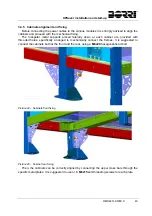
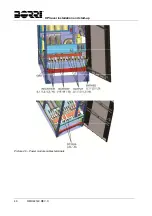
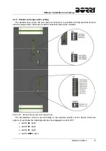
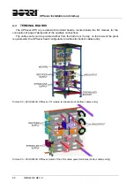
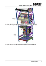
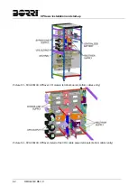
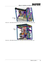
During the electrical installation take particular care to respect the phase rotation. The
terminal boards for cables connection are positioned inside the I/O module, further details are
available at the paragraph "Terminal boards".
Summary of Contents for UPSaver 1000 kVa
Page 2: ...UPS OPERATING MANUAL UPSaver 400 1600 kVA ...
Page 5: ......
Page 7: ...Warnings and general information 2 OMH44148 REV A ...
Page 13: ......
Page 20: ...UPSaver installation and start up OMH44149 REV C 7 ...
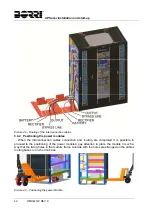
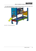
Page 33: ...UPSaver installation and start up 20 OMH44149 REV C Picture 6 Handling of the power module ...
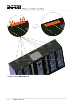
Page 57: ...UPSaver installation and start up 44 OMH44149 REV C Picture 46 UPS cabinets upper fixing ...
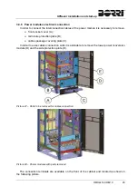
Page 59: ...UPSaver installation and start up 46 OMH44149 REV C Picture 49 Power module cables terminals ...
Page 115: ...UPS user manual 6 OMH44150 REV B ...