


UPSaver
installation and start-up
54
OMH44149 REV. C
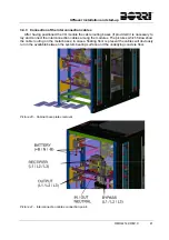
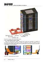
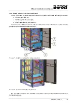
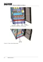
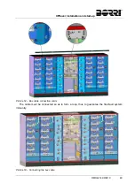
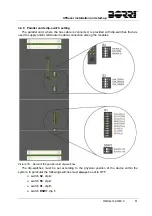
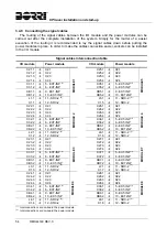
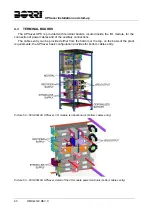
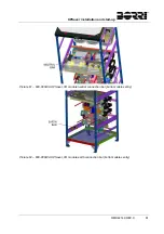
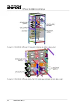
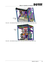
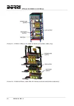
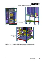
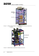
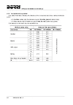
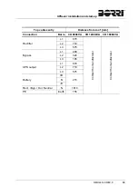
3.4.9 Connecting the signal cables
The routing of the signal cables between the I/O module and the power modules can be
carried out after the complete installation of the system. Simply for the matter of a easier
execution of the routing it is recommended to lay the signal cables down before putting the
power modules in place. In order to make the cables connection easier, sockets can be installed
in the I/O module.
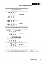
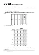
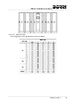
Signal cables interconnection table
I/O
module Power
module
I/O module
Power module
X21.1
X2.1
MODULE 1
X25.1
X2.1
MODULE 5
X21.2
X2.2
X25.2
X2.2
X21.3
X2.3
X25.3
X2.3
X21.4
X2.4
X25.4
X2.4
X31.1
5 - EXT-INP
(1)
X35.1
5 - EXT-INP
(1)
X31.2
6 - EXT-INP
X35.2
6 - EXT-INP
XB1.1
9 - EXT-INP
XB5.1
9 - EXT-INP
XB1.2
10 - EXT-INP
XB5.2
10 - EXT-INP
L1.1
11 - SRC-2
(2)
L5.1
11 - SRC-2
(2)
X1.1
12 - SRC-2
X1.5
12 - SRC-2
X22.1
X2.1
MODULE 2
X26.1
X2.1
MODULE 6
X22.2
X2.2
X26.2
X2.2
X22.3
X2.3
X26.3
X2.3
X22.4
X2.4
X26.4
X2.4
X32.1
5 - EXT-INP
(1)
X36.1
5 - EXT-INP
(1)
X32.2
6 - EXT-INP
X36.2
6 - EXT-INP
XB2.1
9 - EXT-INP
XB6.1
9 - EXT-INP
XB2.2
10 - EXT-INP
XB6.2
10 - EXT-INP
L2.1
11 - SRC-2
(2)
L6.1
11 - SRC-2
(2)
X1.2
12 - SRC-2
X1.6
12 - SRC-2
X23.1
X2.1
MODULE 3
X27.1
X2.1
MODULE 7
X23.2
X2.2
X27.2
X2.2
X23.3
X2.3
X27.3
X2.3
X23.4
X2.4
X27.4
X2.4
X33.1
5 - EXT-INP
(1)
X37.1
5 - EXT-INP
(1)
X33.2
6 - EXT-INP
X37.2
6 - EXT-INP
XB3.1
9 - EXT-INP
XB7.1
9 - EXT-INP
XB3.2
10 - EXT-INP
XB7.2
10 - EXT-INP
L3.1
11 - SRC-2
(2)
L7.1
11 - SRC-2
(2)
X1.3
12 - SRC-2
X1.7
12 - SRC-2
X24.1
X2.1
MODULE 4
X28.1
X2.1
MODULE 8
X24.2
X2.2
X28.2
X2.2
X24.3
X2.3
X28.3
X2.3
X24.4
X2.4
X28.4
X2.4
X34.1
5 - EXT-INP
(1)
X38.1
5 - EXT-INP
(1)
X34.2
6 - EXT-INP
X38.2
6 - EXT-INP
XB4.1
9 - EXT-INP
XB8.1
9 - EXT-INP
XB4.2
10 - EXT-INP
XB8.2
10 - EXT-INP
L4.1
11 - SRC-2
(2)
L8.1
11 - SRC-2
(2)
X1.4
12 - SRC-2
X1.8
12 - SRC-2
(1)
Interconnection card on-board the power module.
(2)
Interconnection card on-board the power module.
Summary of Contents for UPSaver 1000 kVa
Page 2: ...UPS OPERATING MANUAL UPSaver 400 1600 kVA ...
Page 5: ......
Page 7: ...Warnings and general information 2 OMH44148 REV A ...
Page 13: ......
Page 20: ...UPSaver installation and start up OMH44149 REV C 7 ...
Page 33: ...UPSaver installation and start up 20 OMH44149 REV C Picture 6 Handling of the power module ...
Page 57: ...UPSaver installation and start up 44 OMH44149 REV C Picture 46 UPS cabinets upper fixing ...
Page 59: ...UPSaver installation and start up 46 OMH44149 REV C Picture 49 Power module cables terminals ...
Page 115: ...UPS user manual 6 OMH44150 REV B ...