

UPSaver
installation and start-up
OMH44149 REV. C
51
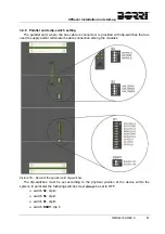
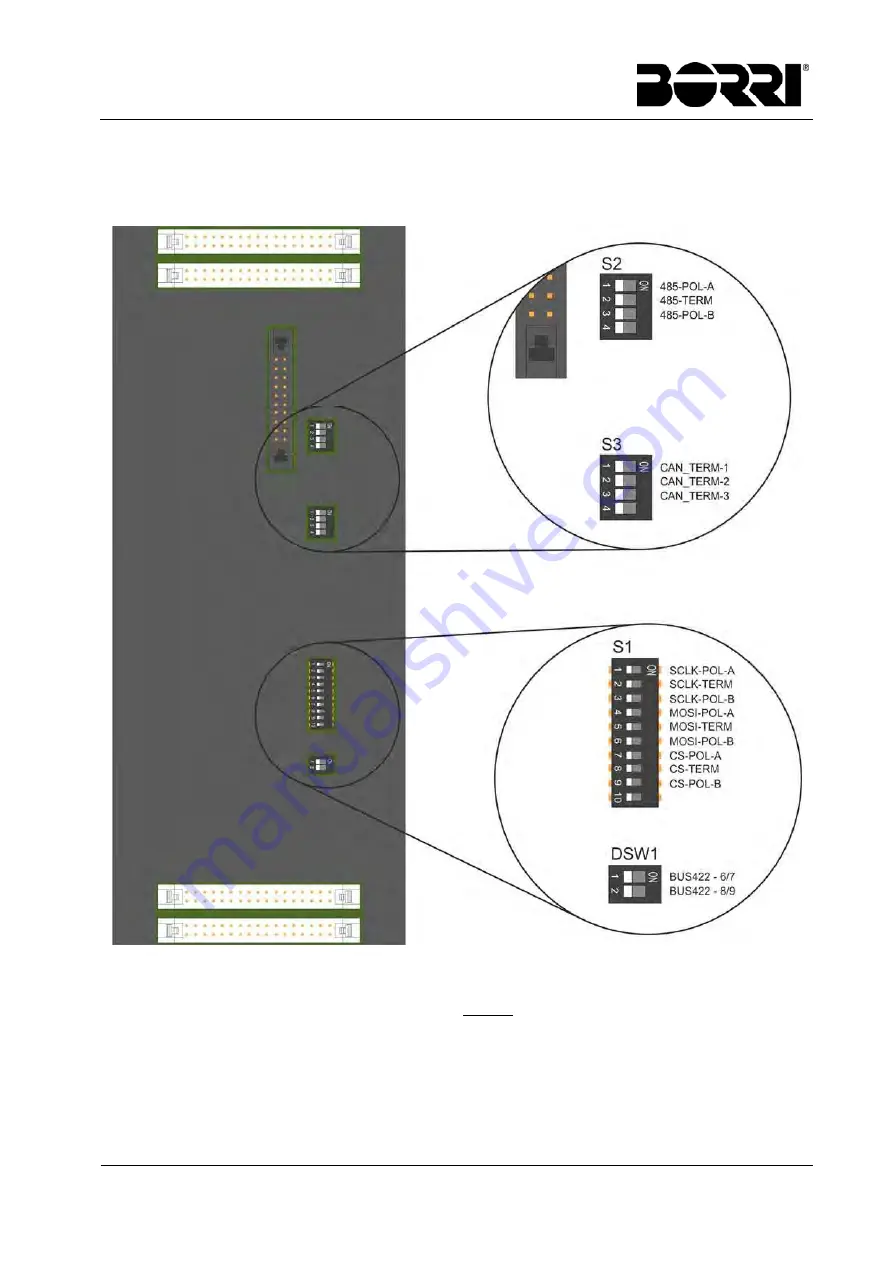
3.4.8 Parallel cards dip-switch setting
The parallel card, where the bus cable is connected, is provided with dip-switches that are
used to supply and/or terminate the data connection among the modules.
Picture 55 – Detail of the parallel card dip-switches
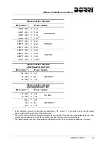
The dip-switches must be set according to the physical position of the device within the
system. In particular the following switches must always be set to OFF:
switch
S2
, dip
4
;
switch
S3
, dip
4
;
switch
S1
, dip
9
;
switch
DSW1
, dip
1
.
Summary of Contents for UPSaver 1000 kVa
Page 2: ...UPS OPERATING MANUAL UPSaver 400 1600 kVA ...
Page 5: ......
Page 7: ...Warnings and general information 2 OMH44148 REV A ...
Page 13: ......
Page 20: ...UPSaver installation and start up OMH44149 REV C 7 ...
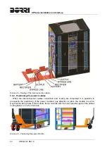
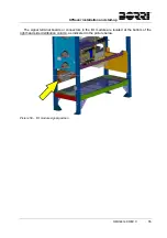
Page 33: ...UPSaver installation and start up 20 OMH44149 REV C Picture 6 Handling of the power module ...
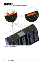
Page 57: ...UPSaver installation and start up 44 OMH44149 REV C Picture 46 UPS cabinets upper fixing ...
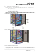
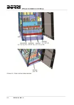
Page 59: ...UPSaver installation and start up 46 OMH44149 REV C Picture 49 Power module cables terminals ...
Page 115: ...UPS user manual 6 OMH44150 REV B ...