

UPSaver
installation and start-up
OMH44149 REV. C
47
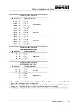
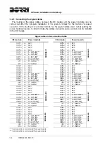
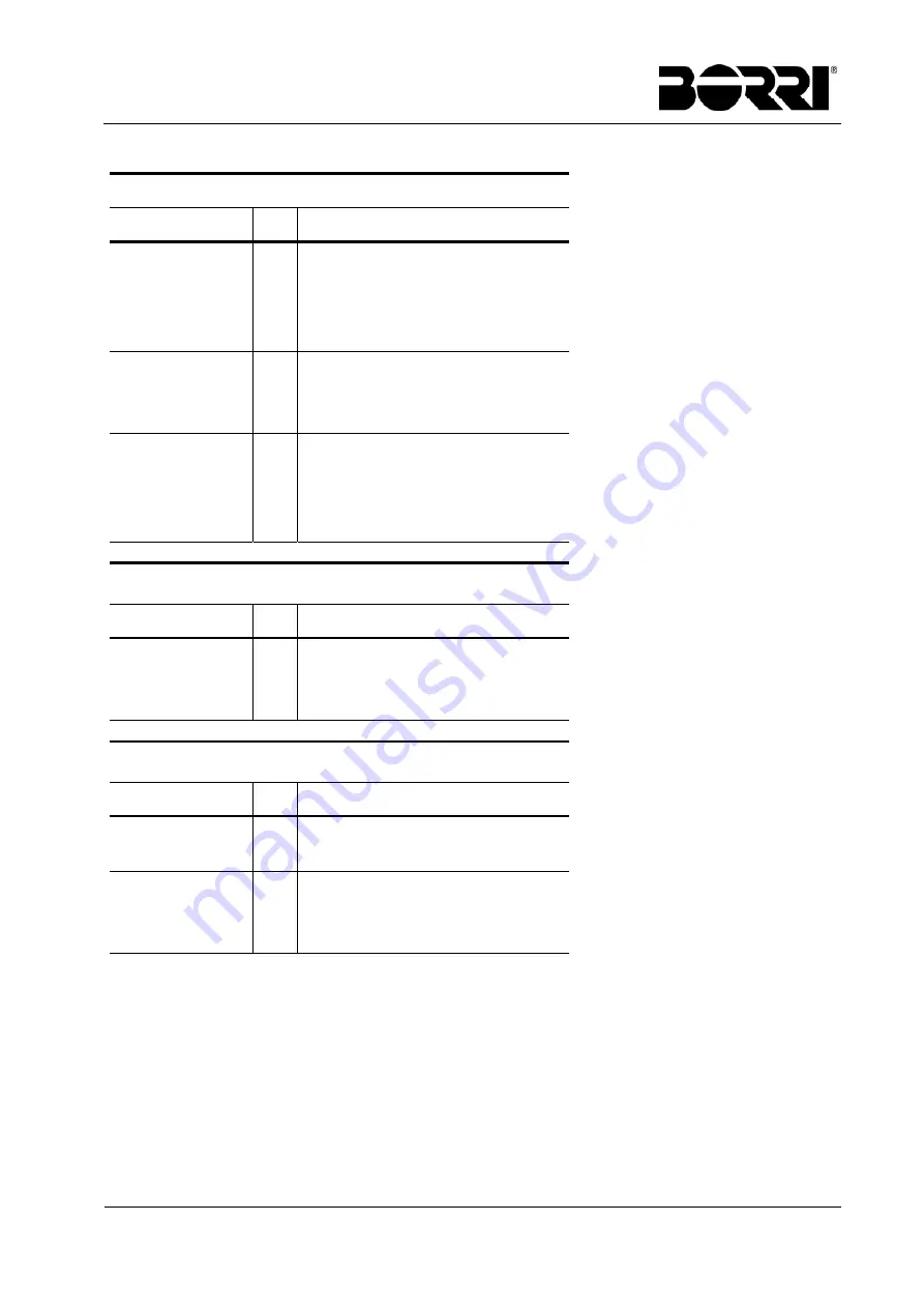
Interconnection terminals
I/O module
(1)
Power
module
L1INP - Mx
1-L1
RECTIFIER
L2INP - Mx
1-L2
L3INP - Mx
1-L3
NING - Mx
1-N
(2)
L1BYP - Mx
2-L1
BYPASS
L2BYP - Mx
2-L2
L3BYP - Mx
2-L3
L1BYP - Mx
3-L1
OUTPUT
L2BYP - Mx
3-L2
L3BYP - Mx
3-L3
NING - Mx
3-N
(2)
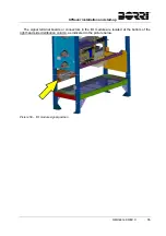
Interconnection terminals
CENTRALIZED BATTERY
I/O module
(1)
Power
module
+B - Mx
+B
BATTERY
N - Mx
N
–B - Mx
–B
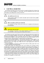
Interconnection terminals
DISTRIBUTED BATTERY
I/O module
(1)
Power
module
+R - Mx
+R
DC BUS
–R - Mx
–R
+Bx
+B
BATTERY
(3)
Nx
N
–Bx
–B
(1)
In the distribution column the terminals are identified as "Mx", where "x" is the number which identifies which
power module must be connected to those terminals.
(2)
The interconnection of the output neutral conductor is not provided. The connection is performed inside the power
module, using a cable which connects the rectifier input and module output neutral terminals.
(3)
The battery terminals are not located inside the distribution column, they are positioned inside the I/O module.
Summary of Contents for UPSaver 1000 kVa
Page 2: ...UPS OPERATING MANUAL UPSaver 400 1600 kVA ...
Page 5: ......
Page 7: ...Warnings and general information 2 OMH44148 REV A ...
Page 13: ......
Page 20: ...UPSaver installation and start up OMH44149 REV C 7 ...
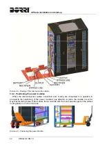
Page 33: ...UPSaver installation and start up 20 OMH44149 REV C Picture 6 Handling of the power module ...
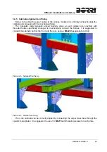
Page 57: ...UPSaver installation and start up 44 OMH44149 REV C Picture 46 UPS cabinets upper fixing ...
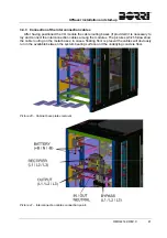
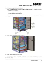
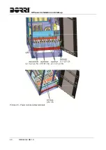
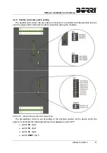
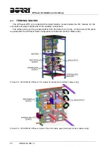
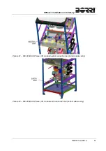
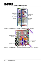
Page 59: ...UPSaver installation and start up 46 OMH44149 REV C Picture 49 Power module cables terminals ...
Page 115: ...UPS user manual 6 OMH44150 REV B ...