

UPSaver
installation and start-up
OMH44149 REV. C
41
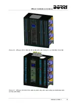
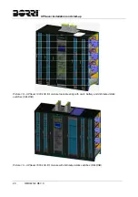
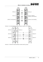
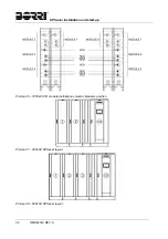
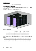
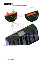
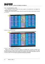
3.4.3 Connection of the interconnection cables
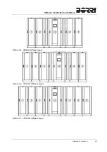
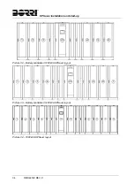
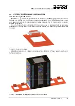
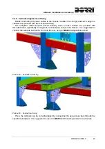
After having positioned the I/O module the cable routing bases (if provided) it is necessary to
lay and connect the interconnection cables among the modules. The pictures which follow show
the cable routing on the metal bases; in case a floating floor is present the cables will obviously
run in the available between the system bearing surface and the underlying concrete floor.
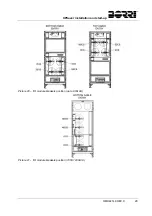
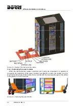
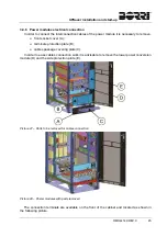
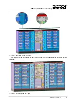
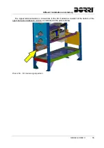
Picture 40 – Cabinet base plates removal
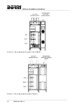
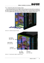
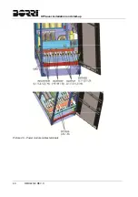
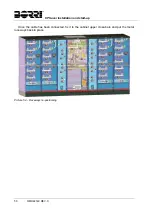
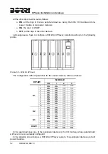
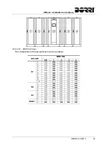
Picture 41 – Interconnection cables connection points
Summary of Contents for UPSaver 1000 kVa
Page 2: ...UPS OPERATING MANUAL UPSaver 400 1600 kVA ...
Page 5: ......
Page 7: ...Warnings and general information 2 OMH44148 REV A ...
Page 13: ......
Page 20: ...UPSaver installation and start up OMH44149 REV C 7 ...
Page 33: ...UPSaver installation and start up 20 OMH44149 REV C Picture 6 Handling of the power module ...
Page 57: ...UPSaver installation and start up 44 OMH44149 REV C Picture 46 UPS cabinets upper fixing ...
Page 59: ...UPSaver installation and start up 46 OMH44149 REV C Picture 49 Power module cables terminals ...
Page 115: ...UPS user manual 6 OMH44150 REV B ...