


UPSaver
installation and start-up
OMH44149 REV. C
5
Picture 74 –
Location of the UPSaver interface cards .......................................................................... 70
Picture 75 –
Touch screen start-up image ............................................................................................ 75
Picture 76 –
I/O module start-up ........................................................................................................... 75
Picture 77 –
Choice of the start-up mode ............................................................................................. 76
Picture 78 –
Module 1 start-up .............................................................................................................. 76
Picture 79 –
Module 1 start-up .............................................................................................................. 77
Picture 80 –
Module 1 start-up .............................................................................................................. 77
Picture 81 –
Module 1 start-up .............................................................................................................. 78
Picture 82 –
Module 1 start-up .............................................................................................................. 78
Picture 83 –
Module 1 start-up .............................................................................................................. 79
Picture 84 –
Module 1 start-up .............................................................................................................. 79
Picture 85 –
Module "n" start-up ........................................................................................................... 80
Picture 86 –
Module "n" start-up ........................................................................................................... 80
Picture 87 –
Battery start-up ................................................................................................................. 81
Picture 88 –
Connection of the system to the load ............................................................................... 81
Picture 89 –
Start-up completed ........................................................................................................... 82
Picture 90 –
Flow diagram .................................................................................................................... 82
Picture 91 –
I/O module start-up ........................................................................................................... 84
Picture 92 –
I/O module start-up ........................................................................................................... 84
Picture 93 –
Module 1 start-up .............................................................................................................. 85
Picture 94 –
Module 1 start-up .............................................................................................................. 85
Picture 95 –
Module 1 start-up .............................................................................................................. 86
Picture 96 –
Module 1 start-up .............................................................................................................. 87
Picture 97 –
Module 1 start-up .............................................................................................................. 87
Picture 98 –
Module "n" start-up ........................................................................................................... 88
Picture 99 –
Module "n" start-up ........................................................................................................... 88
Picture 100 –
Start-up from MBCB ......................................................................................................... 89
Picture 101 –
Start-up from MBCB ......................................................................................................... 89
Picture 102 –
Start-up from MBCB ......................................................................................................... 90
Picture 103 –
Inverters start-up .............................................................................................................. 90
Picture 104 –
Inverters start-up .............................................................................................................. 91
Picture 105 –
Start-up from MBCB completed ....................................................................................... 91
Picture 106 –
Identification of the module to start-up ............................................................................. 92
Picture 107 –
Power module flow diagram ............................................................................................. 92
Picture 108 –
Module start-up confirmation ............................................................................................ 93
Picture 109 –
Module start-up ................................................................................................................. 93
Picture 110 –
Module start-up ................................................................................................................. 94
Picture 111 –
Module start-up ................................................................................................................. 94
Summary of Contents for UPSaver 1000 kVa
Page 2: ...UPS OPERATING MANUAL UPSaver 400 1600 kVA ...
Page 5: ......
Page 7: ...Warnings and general information 2 OMH44148 REV A ...
Page 13: ......
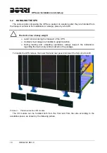
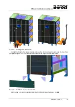
Page 20: ...UPSaver installation and start up OMH44149 REV C 7 ...
Page 33: ...UPSaver installation and start up 20 OMH44149 REV C Picture 6 Handling of the power module ...
Page 57: ...UPSaver installation and start up 44 OMH44149 REV C Picture 46 UPS cabinets upper fixing ...
Page 59: ...UPSaver installation and start up 46 OMH44149 REV C Picture 49 Power module cables terminals ...
Page 115: ...UPS user manual 6 OMH44150 REV B ...