


UPSaver
installation and start-up
4
OMH44149 REV. C
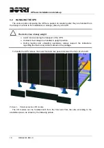
Picture 36 –
Cable routing base ........................................................................................................... 39
Picture 37 –
Installation of cable routing bases on 800 kVA UPSaver ................................................. 39
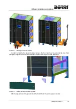
Picture 38 –
Floor fixing ........................................................................................................................ 40
Picture 39 –
Iron base fixing ................................................................................................................. 40
Picture 40 –
Cabinet base plates removal ............................................................................................ 41
Picture 41 –
Interconnection cables connection points ........................................................................ 41
Picture 42 –
Routing of the interconnection cables .............................................................................. 42
Picture 43 –
Positioning the power module .......................................................................................... 42
Picture 44 –
Cabinets front fixing .......................................................................................................... 43
Picture 45 –
Cabinet rear fixing ............................................................................................................ 43
Picture 46 –
UPS cabinets upper fixing ................................................................................................ 44
Picture 47 –
Parts to be removed for cables connection ...................................................................... 45
Picture 48 –
Power modules with parts removed ................................................................................. 45
Picture 49 –
Power module cables terminals ........................................................................................ 46
Picture 50 –
Bus cable raceways .......................................................................................................... 48
Picture 51 –
Removing the bus cable raceways ................................................................................... 48
Picture 52 –
Bus cable connection cards .............................................................................................. 49
Picture 53 –
Connecting the bus cable ................................................................................................. 49
Picture 54 –
Raceways re-positioning .................................................................................................. 50
Picture 55 –
Detail of the parallel card dip-switches ............................................................................. 51
Picture 56 –
600kVA UPSaver .............................................................................................................. 52
Picture 57 –
800kVA UPSaver .............................................................................................................. 53
Picture 58 –
I/O module signal position ................................................................................................ 55
Picture 59 –
600-800kVA UPSaver, I/O module terminal boards (bottom cables entry) ...................... 60
Picture 60 –
600-800kVA UPSaver, detail of the I/O module power terminals (bottom cables entry) . 60
Picture 61 –
600-800kVA UPSaver, I/O module neutral connection bar (bottom cables entry) ........... 61
Picture 62 –
600-800kVA UPSaver, I/O module earth connection bar (bottom cables entry) .............. 61
Picture 63 –
600-800kVA UPSaver, I/O module terminal boards (bottom cables entry) ...................... 62
Picture 64 –
600-800kVA UPSaver, detail of the I/O module power terminals (bottom cables entry) . 62
Picture 65 –
600-800kVA UPSaver, I/O module neutral connection bar (top cables entry) ................. 63
Picture 66 –
600-800kVA UPSaver, I/O module earth connection bar (top cables entry) .................... 63
Picture 67 –
1200kVA UPSaver, I/O module terminal boards (bottom cables entry) .......................... 64
Picture 68 –
1200kVA UPSaver, detail of the I/O module power terminals (bottom cables entry) ....... 64
Picture 69 –
1200kVA UPSaver, centralized battery power terminals (bottom cables entry) .............. 65
Picture 70 –
1200kVA UPSaver, I/O module neutral connection bar (bottom cables entry) ................ 65
Picture 71 –
1200kVA-1400kVA UPSaver, centralized battery power terminals (top cables entry) ..... 66
Picture 72 –
1600kVA UPSaver, detail of the I/O module power terminals .......................................... 66
Picture 73 –
1600kVA UPSaver, detail of the I/O module power terminals .......................................... 67
Summary of Contents for UPSaver 1000 kVa
Page 2: ...UPS OPERATING MANUAL UPSaver 400 1600 kVA ...
Page 5: ......
Page 7: ...Warnings and general information 2 OMH44148 REV A ...
Page 13: ......
Page 20: ...UPSaver installation and start up OMH44149 REV C 7 ...
Page 33: ...UPSaver installation and start up 20 OMH44149 REV C Picture 6 Handling of the power module ...
Page 57: ...UPSaver installation and start up 44 OMH44149 REV C Picture 46 UPS cabinets upper fixing ...
Page 59: ...UPSaver installation and start up 46 OMH44149 REV C Picture 49 Power module cables terminals ...
Page 115: ...UPS user manual 6 OMH44150 REV B ...