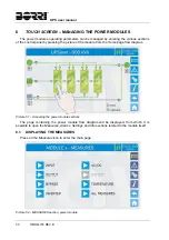
UPS user manual
60
OMH44150 REV. B
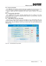
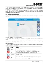
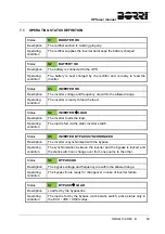
Status
S8
INVERTER MASTER GROUPS SYNCHRONIZED
Description The
UPSaver system is synchronized with the UPSaver MASTER
system with which it is in parallel.
Operating
condition
This status is only present on the SLAVE UPSaver units, and shows
that the inverter is sync with the signal sent by the MASTER UPSaver.
Status
S9
INVERTER MODULES SYNCHRONIZED
Description
The inverter power modules are synchronized to each other.
Operating
condition
The single modules are synchronized with the reference signal sent by
the I/O module.
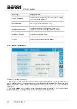
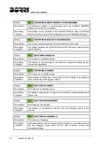
Status
S10
RECTIFIER STANDBY
Description
The rectifier is in standby mode.
Operating
condition
The rectifier is off and ready to be started to charge the battery (Green
Conversion algorithm).
Status
S11
INVERTER STANDBY
Description
The inverter is in standby mode.
Operating
condition
Active status in UHE mode. The inverter is off and ready to be started in
case of anomaly of the bypass mains.
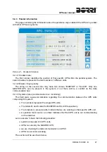
Status
S12
BATTERY STANDBY
Description
The battery is in standby mode.
Operating
condition
The battery static switch is open and the battery is disconnected from
the DC bus.
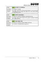
Status
S13
BATTERY DISCHARGING
Description
The battery is discharging.
Operating
condition
The battery is connected to the DC bus and feeding current to the
inverter.
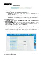
Status
S14
BATTERY IN CHARGE (I)
Description
The battery is charging.
Operating
condition
The battery static switch is closed and the battery is in the first phase of
the I/U charging mode (DIN 41773), with constant current and
increasing voltage.
Summary of Contents for UPSaver 1000 kVa
Page 2: ...UPS OPERATING MANUAL UPSaver 400 1600 kVA ...
Page 5: ......
Page 7: ...Warnings and general information 2 OMH44148 REV A ...
Page 13: ......
Page 20: ...UPSaver installation and start up OMH44149 REV C 7 ...
Page 33: ...UPSaver installation and start up 20 OMH44149 REV C Picture 6 Handling of the power module ...
Page 57: ...UPSaver installation and start up 44 OMH44149 REV C Picture 46 UPS cabinets upper fixing ...
Page 59: ...UPSaver installation and start up 46 OMH44149 REV C Picture 49 Power module cables terminals ...
Page 115: ...UPS user manual 6 OMH44150 REV B ...