UPS user manual
OMH44150 REV. B
51
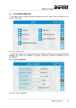
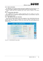
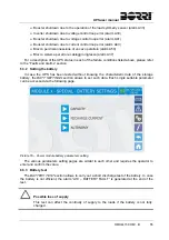
The measures page of a specific section of the module is entered pressing one of the
arrows. The available measures are the same as those related to the UPSaver system that can
be displayed from the Home page.
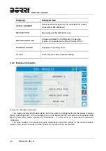
The module battery measures are only available if the system is configured with distributed
battery (DB). The same concepts applies to the bypass measures, which are only available if
the bypass static switch is distributed.
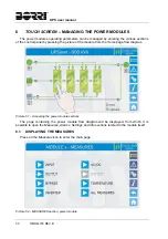
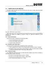
6.2
DIAGNOSTICA DI BASE
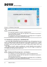
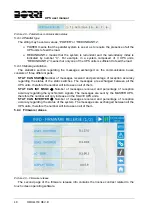
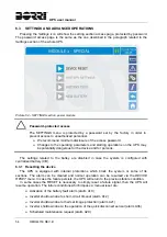
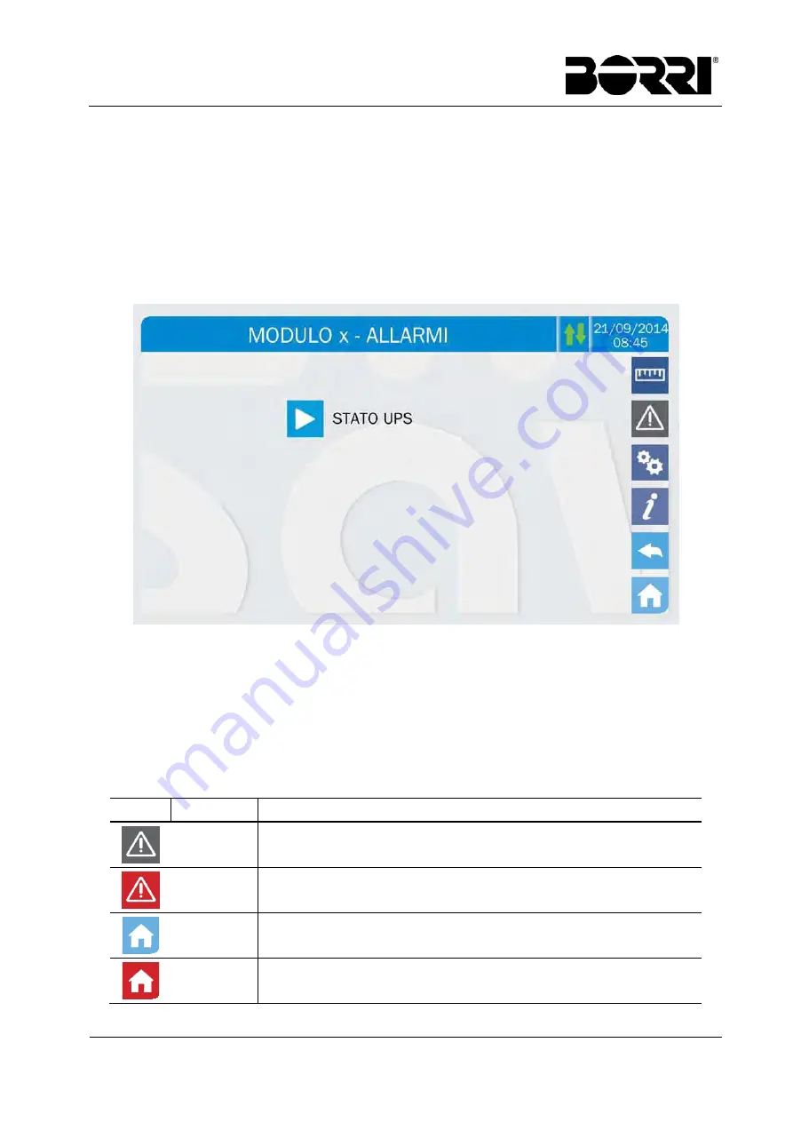
Pressing the Alarms icon will open the page where either the module operating status can be
selected.
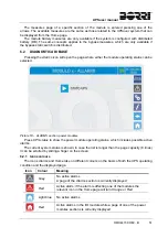
Picture 53 – ALARMS section, power modules
Press UPS status to show the power module operating status, which includes possible active
alarms.
The current system status is shown; in case the list is longer than the page capacity (8 lines)
it can be scrolled by sliding a finger on the screen.
6.2.1 Icons
colours
The icons Alarms and Home take on different colours on the basis of both the UPS operating
condition and the displayed page.
Icon Colour Meaning
Grey
No active alarms
A page of the Alarms section is currently displayed
Red
Active alarm; if the alarm is affecting one of the modules the
relevant icon in the Home page will turn Orange or Red
Light blue
No active alarms
Red
Active alarms in the I/O module while a page of one of the power
modules sections is currently displayed
Summary of Contents for UPSaver 1000 kVa
Page 2: ...UPS OPERATING MANUAL UPSaver 400 1600 kVA ...
Page 5: ......
Page 7: ...Warnings and general information 2 OMH44148 REV A ...
Page 13: ......
Page 20: ...UPSaver installation and start up OMH44149 REV C 7 ...
Page 33: ...UPSaver installation and start up 20 OMH44149 REV C Picture 6 Handling of the power module ...
Page 57: ...UPSaver installation and start up 44 OMH44149 REV C Picture 46 UPS cabinets upper fixing ...
Page 59: ...UPSaver installation and start up 46 OMH44149 REV C Picture 49 Power module cables terminals ...
Page 115: ...UPS user manual 6 OMH44150 REV B ...