
UPS user manual
OMH44150 REV. B
21
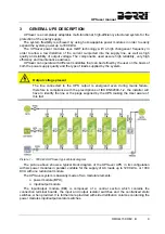
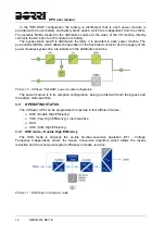
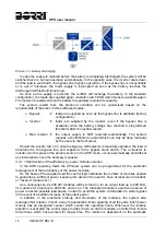
Isolating the power modules
The power modules isolating devices are located inside the I/O module, therefore the
modules are isolated from the input/output sources when the isolators are open.
before carrying out any maintenance operation on the power modules let the
capacitors discharge for at least 5 minutes.
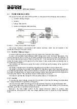
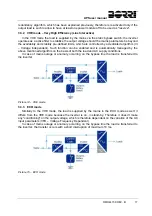
3.4.2 Contactors
The bypass line supply contactor of each module is installed inside the distribution column an
commanded by the ON/OFF push-button SBCBx; the contactor also fulfils the back-feed
protection function.
In case the system is configured with centralized static bypass (CSB) the contactor SBCBx
are not installed.
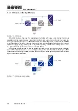
3.4.3 Emergency power off command (EPO)
The emergency power off command is used to disconnect the UPS output immediately,
interrupting the loads supply. It also shuts down the inverter.
Operate the command only in case of real emergency
The components of the system are subject to a high stress when the emergency
power off command is operated under load presence.
Use the emergency power off button only in case of real emergency.
Supply reset
Reset the output supply only when the causes which led to the emergency shutdown
have been eliminated and you are sure that there is no hazard to persons and things.
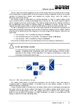
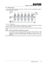
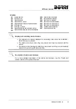
3.4.4 Normal/Bypass
selector
The Normal/Bypass selector Bypass_SW is installed inside the I/O module. It is generally
used during the manual bypass procedure, when it is necessary to isolate the UPS for
maintenance or repair.
Follow the procedures contained in the manual
The Normal/Bypass selector shall only be operated in accordance with the
procedures specified in the installation and start-up section. The manufacturer cannot
accept responsibility for damages arising from incorrect operation.
Summary of Contents for UPSaver 1000 kVa
Page 2: ...UPS OPERATING MANUAL UPSaver 400 1600 kVA ...
Page 5: ......
Page 7: ...Warnings and general information 2 OMH44148 REV A ...
Page 13: ......
Page 20: ...UPSaver installation and start up OMH44149 REV C 7 ...
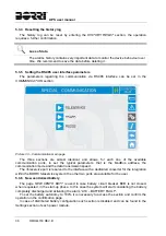
Page 33: ...UPSaver installation and start up 20 OMH44149 REV C Picture 6 Handling of the power module ...
Page 57: ...UPSaver installation and start up 44 OMH44149 REV C Picture 46 UPS cabinets upper fixing ...
Page 59: ...UPSaver installation and start up 46 OMH44149 REV C Picture 49 Power module cables terminals ...
Page 115: ...UPS user manual 6 OMH44150 REV B ...