

UPS user manual
20
OMH44150 REV. B
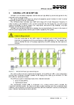
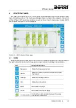
3.4
CONTROL AND OPERATION DEVICES
The control and operating devices of the UPS are listed below.
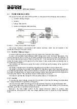
Rectifiers input line isolator (RCBS)
Bypass input line isolator (SBCBS)
UPS output isolator (OCBS)
Manual bypass isolator (MBCBS)
Battery Isolator / Circuit breaker (BCB) - External, inside the battery cabinet
Emergency power off button (EPO)
Normal/Bypass selector
Touch screen control panel
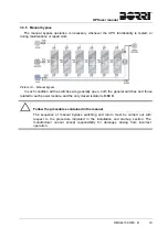
The distribution column located at the I/O module sides houses the isolating devices of the
power modules, as indicated below.
Rectifier input isolator (RCBx)
Bypass line inout AC contactor (Kx)
Pulsante ON/OFF di avvio bypass statico (SBCBx)
Module output isolator (OCBx)
Battery isolator (BCBx)
Check the personnel training
The use of the operation and control devices of the UPS is intended for authorized
personnel only. We recommend to check the training of the personnel responsible for
the use and maintenance of the system.
3.4.1 Isolators (AC inputs, battery and AC output)
The isolators provided on the UPS are used to isolate the power components of the device
from the AC supply line, from the storage battery and from the loads.
Voltage present on terminals
The isolators do not isolate the UPS completely, since AC voltage is still present on
the UPS input terminals. Before carrying out any maintenance on the unit:
Isolate the device completely by operating the external circuit breakers;
Wait at least 5 minutes in order to allow the capacitors to discharge.
Summary of Contents for UPSaver 1000 kVa
Page 2: ...UPS OPERATING MANUAL UPSaver 400 1600 kVA ...
Page 5: ......
Page 7: ...Warnings and general information 2 OMH44148 REV A ...
Page 13: ......
Page 20: ...UPSaver installation and start up OMH44149 REV C 7 ...
Page 33: ...UPSaver installation and start up 20 OMH44149 REV C Picture 6 Handling of the power module ...
Page 57: ...UPSaver installation and start up 44 OMH44149 REV C Picture 46 UPS cabinets upper fixing ...
Page 59: ...UPSaver installation and start up 46 OMH44149 REV C Picture 49 Power module cables terminals ...
Page 115: ...UPS user manual 6 OMH44150 REV B ...