

UPS user manual
16
OMH44150 REV. B
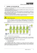
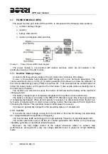
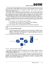
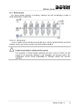
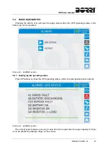
Picture 13 – Battery discharging
In case the supply is restored before the battery is completely discharged, the system will be
switched back to normal operation automatically. In the opposite case, the inverter shuts down
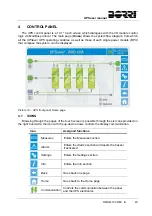
and the load is switched to the bypass line (bypass operation). If the bypass line is not available
or is out of tolerance, the loads supply is interrupted as soon as the battery reaches the
discharge limit threshold (black-out).
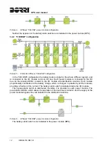
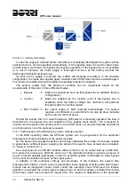
As soon as the supply is restored, the rectifier will recharge the battery. In the standard
configuration, the loads are supplied again via static switch SSB when mains is available again.
The inverter is restarted when the battery has partially restored its capacity.
The system restart from the black-out condition can be customized based on the
requirements of the plant, in three different modes:
Bypass
loads are supplied as soon as the bypass line is available (factory
configuration).
Inverter
loads are supplied by the inverter (even if the bypass line is
available) when the battery voltage has reached a programmed
threshold, after the rectifier restart.
Man. Inverter
the output supply is NOT restored automatically. The system
requires a confirmation to restart which can only be done manually
by the user via the front panel.
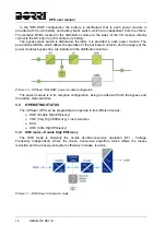
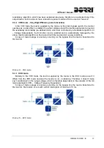
Should the inverter fail, or in case the Bypass_SW selector is manually operated, the load is
transferred to the bypass line and supplied via the bypass static switch. The re-transfer to
inverter, which represent the primary source in the DHE mode, occurs automatically and without
any interruptions once the anomaly is ceased.
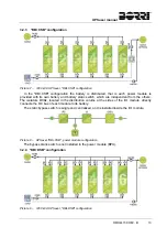
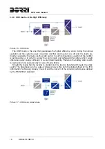
3.3.1.1 Optimization of the efficiency by power modules rotation
In the DHE operating mode the UPSaver system can be programmed for the automatic
management of the redundancy of the power modules.
On the basis of the supplied load the control logic calculates the number of modules needed
to guarantee a sufficient power, keeping into account the need to have at least one redundant,
or "reserve" module (n+1).
As a consequence, 2x 200 kW modules will be turned on for an output load up to 200 kVA,
3x modules for a load up to 400 kVA, and so on. The redundant module is used as a reserve of
power to absorb possible load peaks, in order to avoid the system commutation to static bypass
in the event of a sudden increase of the putput power.
In addition to the automatic start-up and shut-down of the modules, the system also
manages their rotation, in such a way to guarantee a linear agewing of all the parts. Each power
module has an integrated counter which counts the operating hours. Whenever the rotation
algorithm is activated the control logic provides to turn on all the modules, and after that it shuts
down those which have worked for longer time. The rotation is dependent on the automatic
Summary of Contents for UPSaver 1000 kVa
Page 2: ...UPS OPERATING MANUAL UPSaver 400 1600 kVA ...
Page 5: ......
Page 7: ...Warnings and general information 2 OMH44148 REV A ...
Page 13: ......
Page 20: ...UPSaver installation and start up OMH44149 REV C 7 ...
Page 33: ...UPSaver installation and start up 20 OMH44149 REV C Picture 6 Handling of the power module ...
Page 57: ...UPSaver installation and start up 44 OMH44149 REV C Picture 46 UPS cabinets upper fixing ...
Page 59: ...UPSaver installation and start up 46 OMH44149 REV C Picture 49 Power module cables terminals ...
Page 115: ...UPS user manual 6 OMH44150 REV B ...