

UPS user manual
12
OMH44150 REV. B
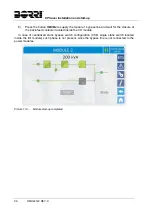
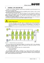
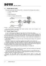
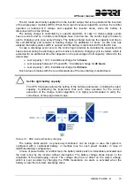
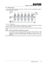
Picture 4 – UPSaver "CB+CSB", power module configuration
Neither the bypass nor the battery static switches are installed in the power module (BPU).
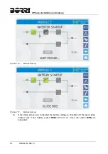
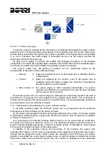
3.2.2 "CB+DSB"
configuration
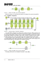
Picture 5 – 1200 kVA UPSaver, "CB+DSB" configuration
In the "CB+DSB" configuration the battery bank is single for the whole UPSaver system, and
is connected to the I/O module common DC bus. Each power module is connected to the DC
bus via the isolators BCBx, located in the I/O module side distribution columns. Each module
proportionally contributes to the battery charge, which is charged in parallel by all the modules,
providing a fraction of the current. The battery static switch is installed inside the I/O module.
The bypass static switch is distributed, therefore it is provided in each power module. The
pus-buttons SBCBx, which allows the operation of the back-feed contactor and the supply of the
power modules bypass line, are installed in the distribution columns.
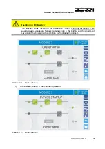
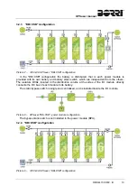
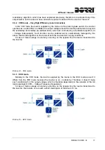
Picture 6 – UPSaver "CB+DSB", power module configuration
The battery static switch is not installed in the power module (BPU).
Summary of Contents for UPSaver 1000 kVa
Page 2: ...UPS OPERATING MANUAL UPSaver 400 1600 kVA ...
Page 5: ......
Page 7: ...Warnings and general information 2 OMH44148 REV A ...
Page 13: ......
Page 20: ...UPSaver installation and start up OMH44149 REV C 7 ...
Page 33: ...UPSaver installation and start up 20 OMH44149 REV C Picture 6 Handling of the power module ...
Page 57: ...UPSaver installation and start up 44 OMH44149 REV C Picture 46 UPS cabinets upper fixing ...
Page 59: ...UPSaver installation and start up 46 OMH44149 REV C Picture 49 Power module cables terminals ...
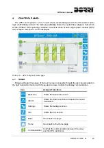
Page 115: ...UPS user manual 6 OMH44150 REV B ...