


UPS user manual
10
OMH44150 REV. B
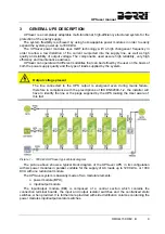
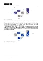
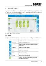
3.1
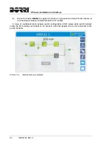
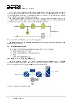
POWER MODULE (BPU)
The power module, part of the UPSaver UPS, is composed of the following main sections:
rectifier / battery-charger;
inverter;
battery static switch;
inverter and bypass static switches.
Picture 2 – Power module (BPU) block diagram
The power module is not provided with isolator switches, which are all installed in the
distribution columns of the I/O module.
3.1.1 Rectifier / Battery-charger
It converts the three-phase voltage of the AC mains into continuous DC voltage.
It uses a three-phase fully-controlled IGBT bridge with a low harmonic absorption. The
control electronics uses a 32 bit
P of latest generation that allows to reduce the distortion of
the current absorbed by mains (THDi) to less than 3%. This ensures that the rectifier does not
distort the supply mains, with regard to the other loads. It also avoids cable overheating due to
the harmonics circulation.
The rectifier is so sized as to supply the inverter at full load and the battery at the maximum
charging current.
The battery charger logic is completely integrated in the rectifier’s control electronics.
The battery is charged, according to the DIN 41773 Standard, every time it has been partially
or completely discharged. When its full capacity is restored, it is disconnected from the DC bus
by means of a static switch, in order to save energy, reduce the stress due to the AC ripple thus
increasing the lifetime. This operating mode is called Green Conversion.
It is however periodically charged but the prevailing state is of complete rest.
3.1.2 Inverter
It converts the direct voltage coming from the rectifier or from the DC battery into alternating
AC voltage stabilized in amplitude and frequency.
The inverter uses IGBT technology with a high switching frequency of approximately 8 kHz.
The control electronics uses a 32 Bit
P of latest generation that, thanks to its processing
capability, generates an excellent output sine-wave.
Moreover, the fully digital control of the output sine-wave allows to achieve high
performances, among which a very low voltage distortion even in presence of high-distorting
loads.
Summary of Contents for UPSaver 1000 kVa
Page 2: ...UPS OPERATING MANUAL UPSaver 400 1600 kVA ...
Page 5: ......
Page 7: ...Warnings and general information 2 OMH44148 REV A ...
Page 13: ......
Page 20: ...UPSaver installation and start up OMH44149 REV C 7 ...
Page 33: ...UPSaver installation and start up 20 OMH44149 REV C Picture 6 Handling of the power module ...
Page 57: ...UPSaver installation and start up 44 OMH44149 REV C Picture 46 UPS cabinets upper fixing ...
Page 59: ...UPSaver installation and start up 46 OMH44149 REV C Picture 49 Power module cables terminals ...
Page 115: ...UPS user manual 6 OMH44150 REV B ...