

UPS user manual
OMH44150 REV. B
9
3
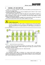
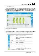
GENERAL UPS DESCRIPTION
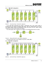
UPSaver is a completely adaptable multi-functional, high-efficiency structured system for the
protection of the energy supply.
The system flexibility is achieved by using hot-swappable power modules in order to easily
expand the system power up to 1600 kVA.
The UPSaver power modules uses IGBT technology with a high changeover frequency in
order to allow a low distortion of the current re-injected into the supply line, as well as high
quality and stability of output voltage. The components used assure high reliability, very high
efficiency and maintenance easiness.
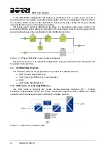
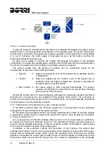
UPSaver can operate with different modalities that can be defined by the user on the basis of
both the power supply quality and the type of loads supplied by the system.
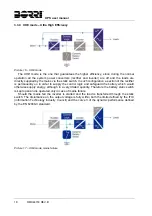
Output voltage present
The line connected to the UPS output is energized even during mains failure,
therefore in compliance with the prescriptions of IEC EN62040-1-2, the installer will
have to identify the line or the plugs supplied by the UPS making the User aware of
this fact.
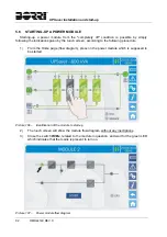
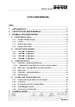
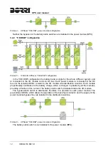
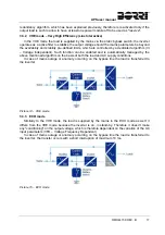
Picture 1 – 1200 kVA UPSaver typical block diagram
The picture above shows a typical block diagram of the UPSaver UPS, in its configuration
with six power modules in parallel, suitable for the supply of AC loads up to 1200 kVA, or 1000
KVA with one redundant module.
The UPSaver system is basically made of two modular elements:
power module (BPU);
input/output module.
The input/output module (I/O) is composed of a central section which contains the
connection terminal boards, the input and output isolator switches and the centralized static
switches, when provided. It is furthermore provided with side distribution columns containing the
power modules input/output isolator switches.
Summary of Contents for UPSaver 1000 kVa
Page 2: ...UPS OPERATING MANUAL UPSaver 400 1600 kVA ...
Page 5: ......
Page 7: ...Warnings and general information 2 OMH44148 REV A ...
Page 13: ......
Page 20: ...UPSaver installation and start up OMH44149 REV C 7 ...
Page 33: ...UPSaver installation and start up 20 OMH44149 REV C Picture 6 Handling of the power module ...
Page 57: ...UPSaver installation and start up 44 OMH44149 REV C Picture 46 UPS cabinets upper fixing ...
Page 59: ...UPSaver installation and start up 46 OMH44149 REV C Picture 49 Power module cables terminals ...
Page 115: ...UPS user manual 6 OMH44150 REV B ...