

UPS user manual
4
OMH44150 REV. B
Index of the pictures
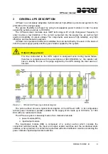
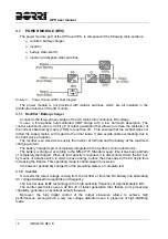
Picture 1 –
1200 kVA UPSaver typical block diagram .............................................................................. 9
Picture 2 –
Power module (BPU) block diagram ..................................................................................... 10
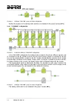
Picture 3 –
1200 kVA UPSaver, "CB+CSB" configuration ...................................................................... 11
Picture 4 –
UPSaver "CB+CSB", power module configuration ............................................................... 12
Picture 5 –
1200 kVA UPSaver, "CB+DSB" configuration ...................................................................... 12
Picture 6 –
UPSaver "CB+DSB", power module configuration ............................................................... 12
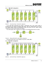
Picture 7 –
1200 kVA UPSaver, "DB+CSB" configuration ...................................................................... 13
Picture 8 –
UPSaver "DB+CSB", power module configuration ............................................................... 13
Picture 9 –
1200 kVA UPSaver, "DB+DSB" configuration ...................................................................... 13
Picture 10 –
UPSaver "DB+DSB", power module configuration ............................................................... 14
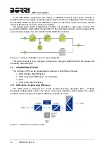
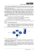
Picture 11 –
DHE Green Conversion mode .............................................................................................. 14
Picture 12 –
DHE mode with battery charging .......................................................................................... 15
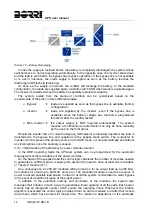
Picture 13 –
Battery discharging ............................................................................................................... 16
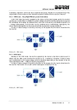
Picture 14 –
VHE mode ............................................................................................................................. 17
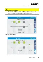
Picture 15 –
ECO mode ............................................................................................................................ 17
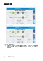
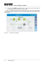
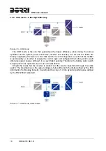
Picture 16 –
UHE mode............................................................................................................................. 18
Picture 17 –
UHE mode, mains failure ...................................................................................................... 18
Picture 18 –
Manual bypass ...................................................................................................................... 19
Picture 19 –
UPS front panel, Home page ................................................................................................ 23
Picture 20 –
MEASURES section ............................................................................................................. 25
Picture 21 –
Input measures page ............................................................................................................ 25
Picture 22 –
ALARMS section ................................................................................................................... 27
Picture 23 –
ALARMS section ................................................................................................................... 27
Picture 24 –
History log, page 1 ................................................................................................................ 28
Picture 25 –
History log, page 2 ................................................................................................................ 29
Picture 26 –
Saving the history log ............................................................................................................ 29
Picture 27 –
Access password to the Settings section ............................................................................. 32
Picture 28 –
SETTINGS section, page 1 ................................................................................................... 32
Picture 29 –
SETTINGS section, page 2 ................................................................................................... 33
Picture 30 –
Clock manual setting ............................................................................................................. 34
Picture 31 –
Clock automatic setting ......................................................................................................... 35
Picture 32 –
Language setting .................................................................................................................. 35
Picture 33 –
Communication main page ................................................................................................... 36
Picture 34 –
Centralized battery parameters setting ................................................................................. 37
Picture 35 –
Centralized battery parameters setting ................................................................................. 37
Picture 36 –
Touch screen network parameters setting ............................................................................ 38
Summary of Contents for UPSaver 1000 kVa
Page 2: ...UPS OPERATING MANUAL UPSaver 400 1600 kVA ...
Page 5: ......
Page 7: ...Warnings and general information 2 OMH44148 REV A ...
Page 13: ......
Page 20: ...UPSaver installation and start up OMH44149 REV C 7 ...
Page 33: ...UPSaver installation and start up 20 OMH44149 REV C Picture 6 Handling of the power module ...
Page 57: ...UPSaver installation and start up 44 OMH44149 REV C Picture 46 UPS cabinets upper fixing ...
Page 59: ...UPSaver installation and start up 46 OMH44149 REV C Picture 49 Power module cables terminals ...
Page 115: ...UPS user manual 6 OMH44150 REV B ...