OPERATING MANUAL
Stand 11/2020
Please read before commissioning!
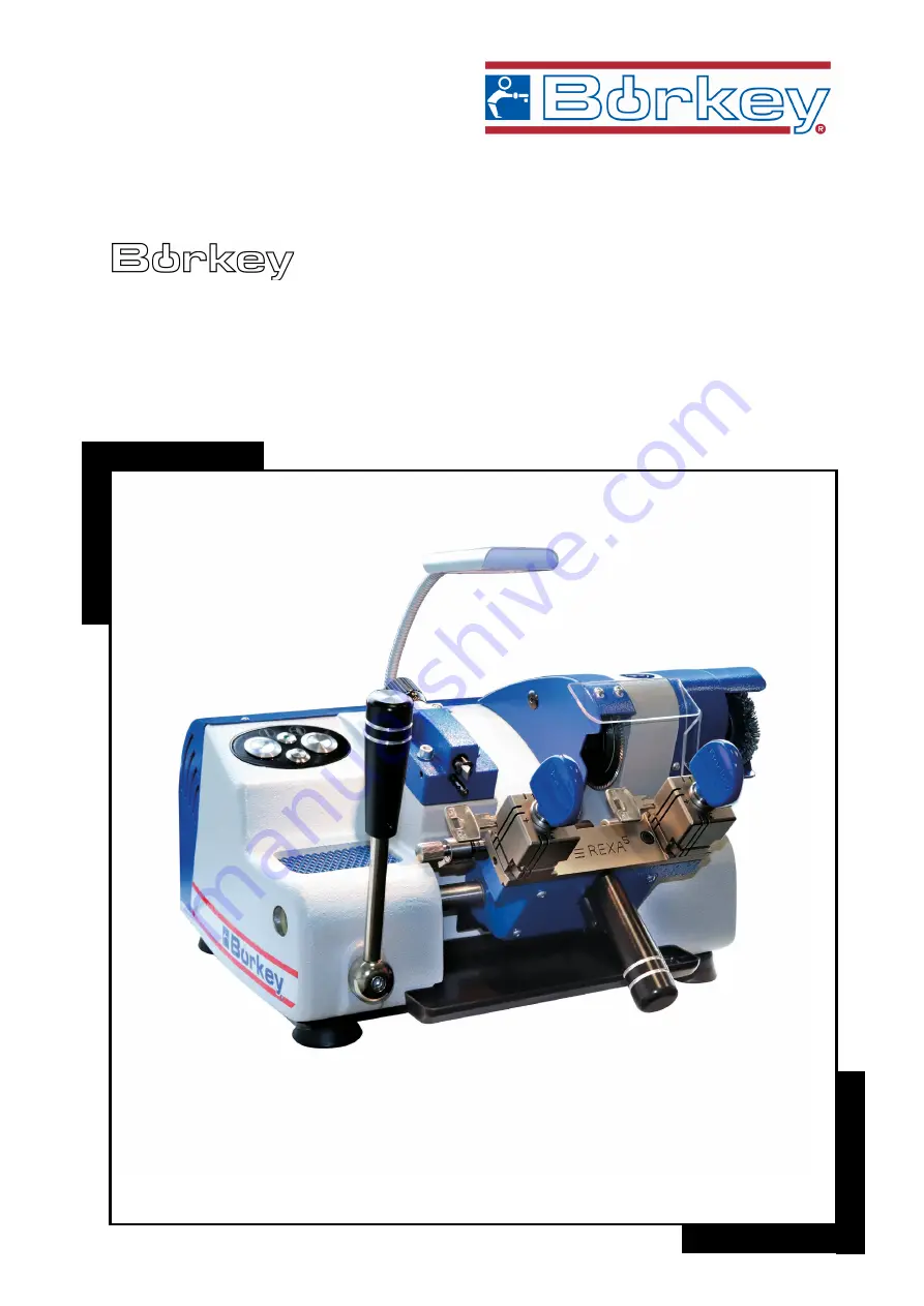
919 REXA
5
Page 1: ...OPERATING MANUAL Stand 11 2020 Please read before commissioning 919 REXA5...
Page 2: ...contents are prohibited if not expressly permitted beforehand Contraventions will compel you to be liable for damages All rights for the case of patent application as well as utility model and design...
Page 3: ...ely Subsequent complaints cannot be considered It is absolutely necessary to state the machine type and the machine number in all queries and spare parts orders See type label Machine disposal The tra...
Page 4: ...tallations 8 5 Notes for usage the machine 9 6 Description 9 7 Technical data 9 8 Accessories 10 9 Wiring diagram 10 10 Maintenance 11 11 Main function parts 12 12 Spare part list 14 13 Working notes...
Page 5: ...has to be available at the operating site of the machine Any person working with and on the machine must read and make use of the operating manual for works including Operating including setting up tr...
Page 6: ...perated outdoors in explosion prone areas or in immediate vicinity to flammable substances The installation site should be selected in a way so that the electrical supply line with Schuko socket and 0...
Page 7: ...sion 9 Categorically no safety installations must be modified disassembled or taken out of commission The safety installations prevent damages 10 Secure the machine in a way so that it cannot be activ...
Page 8: ...moved from their positions by the cutter torques 4 Safety installations In order to ensure risk free working with our machine 912 REXA we have provided the following safety installations and thereby...
Page 9: ...ures of the machine Copies any cutting angle in the roll off method without changing the cutter Quickly adjustable 4 way reversible jaw Exchangeable wear parts Maintenance free sintered bushings mount...
Page 10: ...4 9000 022 004 9 1 allen key SW 8 9000 022 010 10 1 spanner SW24 9000 023 003 11 1 spanner SW 10 9000 023 008 9 Wiring diagram 1 Power on off switch complete 9 912 013 006 2 Power on off switch adjust...
Page 11: ...he spring tension mounted beneath the key holder To do that remove the key holder sheet and loosen the setscrew of the spring tightening coupling Turn the spring tightening coupling upwards using a pi...
Page 12: ...utter 5 Loosen the tightening nut 4 by using a jaw spanner SW 24 in clockwise rotation Insert allen key SW 8 into the cutter shaft as a brace to avoid twisting of the cutter shaft Remove tools and ins...
Page 13: ...Safeguard key holder 10 The safeguard always holds the key holder 9 in starting position for preparatory works Unlock for working position by pulling it up It can only be operated if the stop levers 8...
Page 14: ...Swarfs protection 9994 014 007 Swarfs trough 9912 012 006 Feed lever complete 9912 009 002 Stop lever 9919 009 003 Collet stop plate left 9919 009 004 Collet stop plate right 9919 009 002 Stop plate 9...
Page 15: ...p lever and then fasten it then put the stop lever back Keys with the same stop collar on both sides can be fastened against the left clamping jaw sides directly Use clamping jaw 4 for very deep cuts...
Page 16: ...plates into the right grooves of the clamping jaw stop plate stop plate with gap Starting position cutting Turn the machine on activate pressure switch 1 Unlock the key holder see page 10 Hold on care...
Page 17: ...ten against the right side of the clamping jaw Lead the key holder to the feeler and cutter It now should be possible to set both feeler and cutter evenly into the cuts of the setting gauges Re settin...
Page 18: ...4 Page 3 Profile guidance on the bottom for keys which profile frames or incisions do not facilitate flawless clamping or aligning in the clamping 1 and 4 Page 4 Back fastening position for cutting de...
Page 19: ...ver the pulleys Stretch the belts by shifting the engine Re tighten the engine and re install the machine cap and the wire brush Engine and cutter shaft cannot be rotated Contact customer support Incr...
Page 20: ......