Page
9
of
13
2.3.3 Changing the MIDI Channel DIP Switches
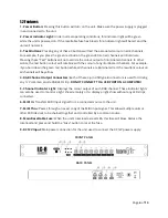
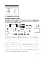
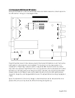
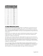
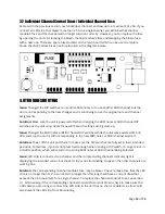
Setting the DIP switches on the main board determines which MIDI channel the unit will respond to.
See DIP switches 1 through 4 in the diagram below.
These DIP switches are set in the same way in which the channel DIP switches are set. That is, when
a DIP
switch is in the up position, it is considered “1”
and, when it is in the down position, it is
considered “0”.
These binary codes are used to configure the MIDI channel in which the unit will
respond to. For example, if only DIP switch 4 is in the up position on the main board while the other
switches are in the down position (resulting in the binary code 0001), the unit will respond to MIDI
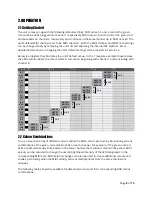
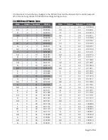
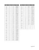
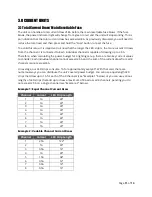
channel 2. Refer to the
“Binary” column on the
table in section 2.3.4 for the DIP switch positions
required to change the unit’s designated MIDI channel.
The default DIP switch setting is highlighted
in grey.
Again, it is important to note that any changes to the DIP switches must be done while the unit is
powered off, as the unit only checks the DIP switch settings during start-up.


