


User’s Manual
71
7.
A
PPENDICES
7.1.
A
PPLICATION
N
OTES
7.1.1.
S
IZING YOUR BRAKING REQUIREMENTS
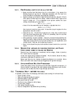
Braking transistor modules are sized by peak current requirements and
system voltage. Please use the following guidelines:
•
Verify the amount of peak power needed for braking. This must be
determined from the mechanical system layout, and should be calculated
in either peak watts or horsepower.
•
VFD’s are rated for braking power as well as peak braking capacity. This
information is available in the drive manual. This will be the maximum
amount of power that the output inverter stage of the VFD can absorb
from the load before having an overcurrent condition. Refer to your VFD
documents for information on drive sizing. Keep in mind that the current
rating of the drive is for three phase current, not DC bus current. The
braking current in the DC bus will be higher than the AC current absorbed
from the load.
•
Because Bonitron braking transistor modules are rated for peak current,
determine the
peak
braking power required.
7.1.1.1.
H
ORSEPOWER TO
W
ATTS
Once the braking requirements for the mechanical load are determined,
multiply the horsepower by the scaling factor of 746 to determine the
wattage required. For instance, with a 400 HP system, the peak braking
power may be 600 HP. In this case the peak power required would be:
746
*
.
.
Braking
brake
P
H
P
=
watts
P
H
P
brake
447600
746
*
.
.
600
=
=
7.1.1.2.
P
EAK
A
MPERAGE
The peak amperage of the braking cycle can be determined by dividing
the peak braking wattage by the system bus trip point of the braking
transistor module used. If the above example were on a 480 VAC system,
the trip point is 750 VDC, as determined from Table 2-3: In this case the
peak current required would be:
VDC
P
I
Braking
brake
750
/
.
=
596.8ADC
750
/
447600
=
=
VDC
watts
I
brake
In this case, a 600 Amp module should be used.
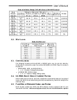
7.1.1.3.
O
HMIC
V
ALUE
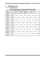
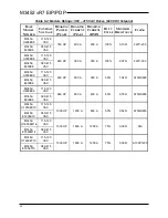
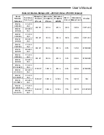
The ohmic value of the resistive load can usually be determined from the
Tables in Section 6-1. The ohmic value shown indicates the capacity of
the braking transistor module, and may not be directly related to the
horsepower of the drive. In order to calculate the required ohmic value
for the braking load, use the following formula:
brake
DCbus
brake
P
V
R
2
)
(
=
The DC bus voltage for the equation is determined by the level that the
drive begins braking. For 460/480 VAC systems, this is typically 750
Summary of Contents for M3452
Page 14: ...M3452 vR7 EIP PDP 14 This page intentionally left blank ...
Page 19: ...User s Manual 19 Figure 3 2 Customer Connections in K9 Chassis CUSTOMER I 0 CONNECTION ...
Page 21: ...User s Manual 21 Figure 3 2 Customer Connections in M14 Chassis CUSTOMER I O CONNECTION ...
Page 24: ...M3452 vR7 EIP PDP 24 Figure 3 6 I O Hookup with R7 EIP PDP Communication ...
Page 26: ...M3452 vR7 EIP PDP 26 Figure 3 8 24VDC Power Connection ...
Page 58: ...M3452 vR7 EIP PDP 58 This page intentionally left blank ...
Page 66: ...M3452 vR7 EIP PDP 66 Figure 6 3 M3452 K9 Chassis Dimensional Outline Drawing ...
Page 68: ...M3452 vR7 EIP PDP 68 Figure 6 5 M3452 M14 Chassis Dimensional Outline Drawing ...
Page 75: ...User s Manual 75 NOTES ...
Page 76: ...M3452 vR7 EIP PDP 76 This page intentionally left blank ...
Page 77: ......
Page 78: ......
Page 79: ......