Operating Instructions
The bp408 Safety Circuit
General Information EC Type Examination Safety Circuit
www.boehnkepartner.de
Page 1: ...Operating Instructions The bp408 Safety Circuit General Information EC Type Examination Safety Circuit www boehnkepartner de...
Page 2: ...anual does not provide exhaustive information on our entire set of delivery options Irrespective of the attention paid during creation of texts images and programs we cannot assume legal liability for...
Page 3: ...ation 11 3 2 3 Notes on function 12 3 2 4 Notes on test 12 3 3 bp408 testing program 14 3 3 1 General testing sequence 14 3 3 1 1 Step 1 14 3 3 1 2 Step 2 16 3 3 1 3 Step 3 16 3 3 2 Extra requirements...
Page 4: ...4 5 Connection of SPL 01 23 4 6 Safety circuit status bar on display 23 5 Technical data 24...
Page 5: ...prove clarity and structur ing the manual was divided into multiple parts The In struction Manual of the bp408 Safety Circuit also considers the dangers and risks which may lead to severe health re la...
Page 6: ...s only permitted given the consent of B hnke Partner GmbH and under the inclusion of a pre cise indication of source B hnke Partner GmbH its logo and the company desig nated are protected trademarks T...
Page 7: ...ntains a safety circuit The safety circuit can be used in the following cases in accordance with EN 81 20 50 Preparatory measures with opened elevator cabin door and elevator shaft door Approach with...
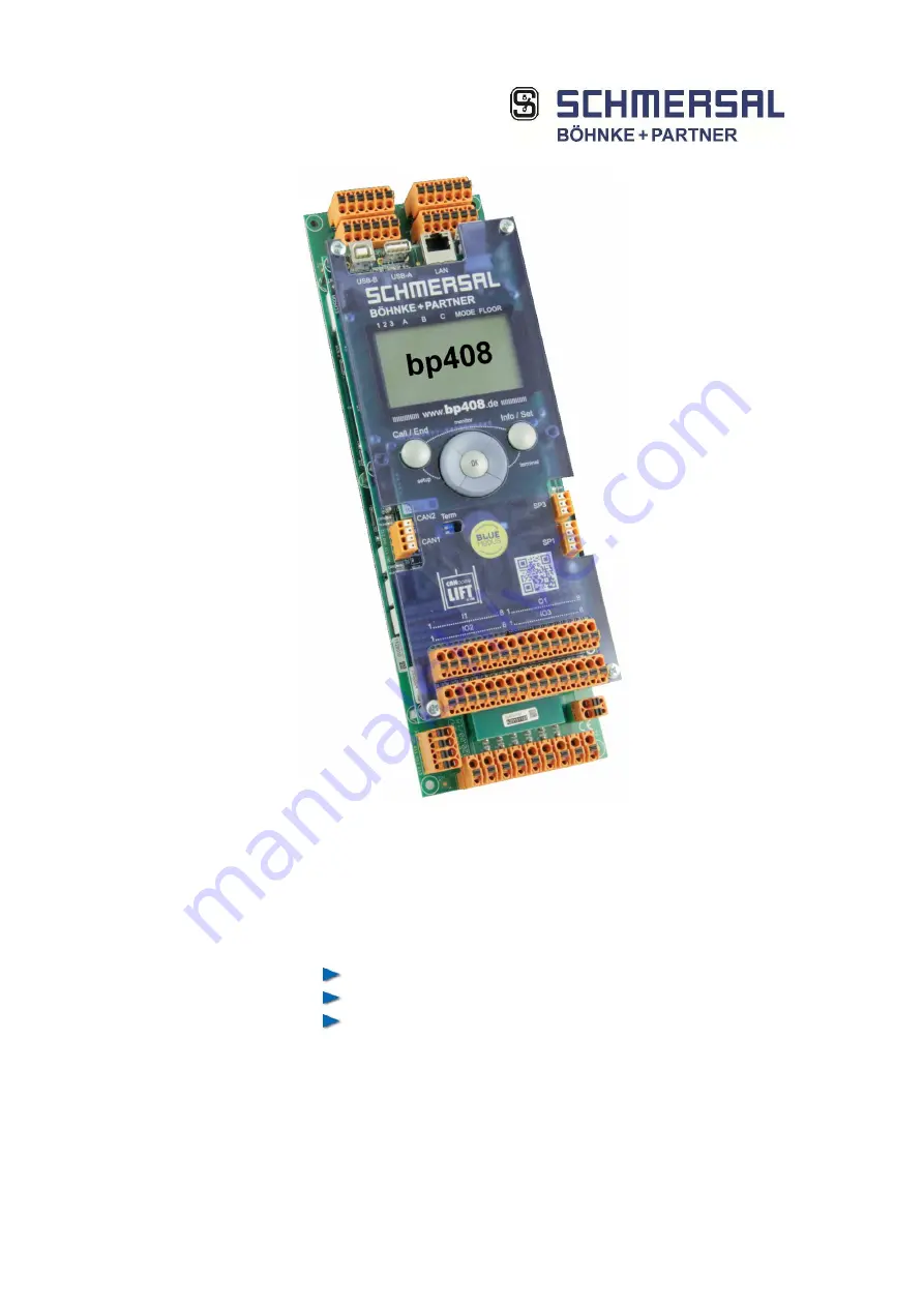
Page 8: ...8 Figure 2 bp408 system module Section of SPC 01 circuit board Reg No 01 208 5A 6135 00 18...
Page 9: ...9 2 2 Declaration of conformity Figure 3 Declaration of conformity...
Page 10: ...max 1 2 m above the level position There must be a resid ual space of at least 1 0 m between the cabin floor and the upper edge of the shaft access The apron fitted beneath the cabin may only al low...
Page 11: ...fil at least protection class IP2xD Condensation must be avoided on all components Example Water condensation in damp machine room after the control system is switched off In critical environments ple...
Page 12: ...circuit SMZ on SPL 01 is used for UCM con trol A magnetic switch is sufficient for channel 1 and a position signal from the lift controller for channel 2 e The reaction times of all components must b...
Page 13: ...module for support purposes f The specialists check the provided acceptable limit val ues of EN 81 20 50 and or EN 81 1 2 A3 for example distances on the elevator system by measuring g The specialist...
Page 14: ...peed monitoring of the lift controller is disabled 3 3 1 1 Step 1 In order to check this function prior to commissioning the bp408 system module contains a test program The test pro gram is activated...
Page 15: ...sing the di rectional key in the downward direction This is described in the following chapter If a testing sequence with closed doors is selected it is checked whether the safety circuit has been int...
Page 16: ...description pertaining to each inverter is provided on request Here the brake and trip contactors are actuated with the door opened and the safety circuit activated until the safety circuit triggers a...
Page 17: ...switch is activated The elevator will now move with the maximum rated speed or only by opening the brake A braking system tested in accordance with UCM engages and brings the cabin to a stop The trav...
Page 18: ...without a brake on the traction sheave certified in accordance with UCM suitable braking or arresting systems are prescribed in order to sat isfy EN 81 20 Usually a suitable speed limiter with magneti...
Page 19: ...check these for flawless operation the inputs on the control system must be disconnected and or provided with a con tinuous signal 24 V The system module detects an erro neous sequence of signals in n...
Page 20: ...A 12B 13 14 correspond to DIN EN 60664 and or DIN EN 60950 The safety circuit with query unit on bp408 is secured up to a maximum of 2 A The connection of neutral conductor mains potential NN is made...
Page 21: ...of the control relay K552 may engage first but only if relays K551 K553 and K554 have disengaged By engaging K552 K553 is al lowed to engage which causes the engagement of K554 in turn If relays K553...
Page 22: ...open continuously During approach and readjustment with the cabin door opened an error therefore causes no bypassing of the door and door lock switch This means that the unlocking zone can only be ap...
Page 23: ...tus bar is provided on the right side of the display It is shown in all menus The safety circuit sta tus bar provides the following information Pos Meaning Terminal 1 Passive Safety Circuit 10 2 Emerg...
Page 24: ...A Fuse safety circuit max 2 A Control power supply 24 VDC 10 15 Reaction time UCM detection max 10 ms Protection degree Modul IP20 Housing IP43 Operating temperature 0 C bis 60 C Storage transport te...