background image

Artisan Technology Group 

is your source for quality 

new and certified-used/pre-owned equipment

• 

FAST SHIPPING AND 

DELIVERY

• 

TENS OF THOUSANDS OF 

IN-STOCK ITEMS

•  EQUIPMENT DEMOS
• 

HUNDREDS OF 

MANUFACTURERS 

SUPPORTED

•  LEASING/MONTHLY


RENTALS

•  ITAR CERTIFIED


SECURE ASSET 

SOLUTIONS

SERVICE CENTER REPAIRS

Experienced engineers and technicians on staff 

at our full-service, in-house repair center

WE BUY USED EQUIPMENT

Sell your excess, underutilized, and idle used equipment 

We also offer credit for buy-backs and trade-ins

www.artisantg.com/WeBuyEquipment


REMOTE INSPECTION

Remotely inspect equipment before purchasing with 

our interactive website at


www.instraview.com

LOOKING FOR MORE INFORMATION? 

Visit us on the web at


www.artisantg.com


for more 

information on price quotations, drivers, technical 

specifications, manuals, and documentation

Contact us:


(888) 88-SOURCE  |  [email protected]  |  www.artisantg.com

SM

View

Instra

Summary of Contents for PACESETTER 2701

Page 1: ...l service in house repair center WE BUY USED EQUIPMENT Sell your excess underutilized and idle used equipment We also offer credit for buy backs and trade ins www artisantg com WeBuyEquipment REMOTE INSPECTION Remotely inspect equipment before purchasing with our interactive website at www instraview com LOOKING FOR MORE INFORMATION Visit us on the web at www artisantg com for more information on ...

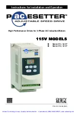
Page 2: ...ation High Performance Drives for 3 Phase AC Induction Motors 115V MODELS 115V MODELS n n Model 2701 1 4 HP n n Model 2703 1 2 HP P N 074 01023A BW Artisan Technology Group Quality Instrumentation Guaranteed 888 88 SOURCE www artisantg com ...

Page 3: ...h could injure personnel or damage the control motor or other equipment If you have any doubts about how to connect the control or motor refer to the detailed sections of this manual FIGURE 1 Basic Connection Diagram Refer to noted pages for details Function F25 returns all functions to their factory settings Artisan Technology Group Quality Instrumentation Guaranteed 888 88 SOURCE www artisantg c...

Page 4: ...l 11 Step 5c Ground the Inverter 12 Step 5d Connect Circuit Breaker 12 Step 5e Connect AC Line 12 Step 6 Check System Before Starting 13 OPERATION 14 Step 7 Operate the Control 14 Step 7a Operate Inverter Using Keypad 14 Step 7b Operate Inverter Using Remote Devices optional 14 Step 7c Change Other Parameters optional 15 Parameter List 15 Parameter Descriptions 17 TROUBLESHOOTING 23 WARRANTY 27 co...

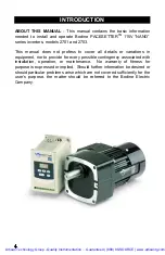
Page 5: ...ent nor to provide for every possible contingency associated with installation operation or maintenance No warranty of fitness for purpose is expressed or implied Should further information be desired or should particular problems arise which are not covered sufficiently for the user s purpose the matter should be referred to the Bodine Electric Company Artisan Technology Group Quality Instrumenta...

Page 6: ...ttern 3 Patterns each for 50 Hz 60 Hz Overload protection 150 for 1 min Over voltage DC voltage 410V Under voltage DC voltage 200V Momentary Power Loss 0 2 seconds inverter can be restarted by speed search Stall Prevention Accelerate Decelerate Constant speed Output terminal short circuit Electronic circuitry protection Grounding fault Electronic Circuitry protection Protection features Other func...

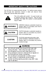
Page 7: ...rdous situation which if not avoided may result in minor or moderate injury CAUTION CAUTION used without the safety alert symbol indicates a potentially hazardous situation which if not avoided may result in property damage WARNING l Do not touch printed circuit board PCB right after turning off power Wait until power light turns off l Do not attempt to wire circuitry while power is on l Do not at...

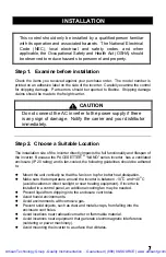
Page 8: ...tly impacts the full functionality and lifespan of the inverter Because the PACESETTER TM NANO series inverter has a ventilated enclosure IP 20 rating and is fan cooled the following guidelines should be adhered to l Mount the unit vertically so that the fan is on top for better heat dissipation l Make sure the temperature around the inverter is between 10 O C and 40 O C avoid locations in direct ...

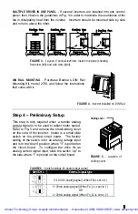
Page 9: ...nserting screws through the three 4 5 mm diameter holes in the enclosure base DIMENSION Millimeters Inches A 132 5 20 B 116 4 57 C 130 5 12 D 8 2 0 32 E 118 4 64 F 61 2 40 G 72 2 83 FIGURE 2 Mounting dimensions Artisan Technology Group Quality Instrumentation Guaranteed 888 88 SOURCE www artisantg com ...

Page 10: ... current signal is to be used to adjust motor speed Refer to Fig 5 and remove the small sliding cover on the side of the inverter Inside is a small slide switch on the printed circuit board The factory setting of the switch is for an analog voltage input and is in the down position where V is printed on the circuit board To configure the drive for an analog current signal input slide the switch up...

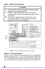
Page 11: ... Speed Pot 10 0V Common for Analog Input Speed Pot and Analog Output 11 Analog Output FIGURE 7 Electrical connections with remote inputs and outputs Step 5a Connect the Motor Connect a 230 VAC three phase squirrel cage induction motor with appropriate ratings for the inverter to the T1 T2 and T3 screw terminals on terminal block TM1 Use a Phillips screwdriver to clamp the stripped motor wires Tigh...

Page 12: ...a switch with low voltage contacts to screw terminals 7 and 5 on terminal block TM2 Close the switch to reset the drive after a fault condition The function of this switch input can be changed with programmable function F20 SPEED SIGNAL INPUT Vin To make this input functional programmable parameter F11 must be changed to 001 or 002 refer to Step 7 for procedure Use 20 AWG wire to connect a remote ...

Page 13: ... loops when grounding several inverters together FIGURE 8 Grounding multiple drives The two circuits on the left are correct The circuit on the right creates a ground loop and is incorrect Step 4h Connect Circuit Breaker Connect a 2 pole circuit breaker between terminals L1 L2 on terminal block TM1 and the 115 VAC single phase supply Step 5d Connect the AC Line Connect the 115 VAC single phase pow...

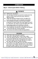
Page 14: ... is on l Do not attempt to examine the components and signals on the PCB while the inverter operating l Do not touch the heat sink base during operation CAUTION l Check that motor is securely mounted l Test motor unloaded first to verify proper setup l Check all rotating members Be sure keys pulleys etc are securely fastened and safety guards are in place l Check for proper mounting and alignment ...

Page 15: ...art and accelerate 3 Press the button labeled p to increase the output frequency The motor will accelerate until the p button is released Note that the output frequency changes at a progressively faster rate the longer you hold the button down Press the q button to decrease the output frequency 4 Press the button labeled RUN STOP again to stop the motor 5 If the motor does not start promptly and r...

Page 16: ...rst stop the motor if necessary Only acceleration time F01 deceleration time F02 motor direction F04 and torque compensation F13 can be changed while motor is running Use the same procedure described in Step 7b to change other parameters The following pages give a brief description of each parameter To clear the inverter of all changes and return it to the factory settings change function F25 to 0...

Page 17: ...P1 003 Emergency stop 004 External Base Block 005 Reset 006 SP2 002 F20 Input terminal 7 function 001 Jog 002 SP1 003 Emergency stop 004 External Base Block 005 Reset 006 SP2 005 F21 Output terminal function 001 Operating 002 Frequency reached 003 Fault 003 F22 Reverse enable 000 REV command enabled 001 REV command disabled 000 F23 Auto restart enable 000 Auto restart enabled 001 Auto restart disa...

Page 18: ... on the digital control panel it is possible to change motor direction without changing the motor connection by changing function F04 The factory setting is 000 for forward direction Changing F04 to 001 will result in reverse direction NOTE When F22 001 reverse is disabled and F04 can not be set to 001 If it is the keypad indication will display the error message LOC F05 V F Pattern Setting Functi...

Page 19: ...y limit and hence the minimum motor speed limit by changing F07 from the factory setting of 00 0 0 0 Hz to any number between 00 0 and 200 in increments of 0 1 Hz up to 100 Hz and increments of 1 Hz after that If F07 00 0 and the frequency command F07 the inverter will output according to F07 setting F08 Preset Speed 1 SP1 Frequency Change the frequency of the SP1 input by changing F08 from the fa...

Page 20: ... run hotter than normal Additional cooling may be required or a motor smaller than the normal rating should be used Although IGBT TYPE inverters can provide a low audible noise environment during operation it is possible that high frequency switching may interfere with external electronic components or other controllers F13 Torque compensation gain Function F13 changes torque compensation gain fro...

Page 21: ...ction Input Terminal 7 F19 changes the function of input terminal 6 factory setting is Preset Speed 1 and F20 changes the function of input terminal 7 factory setting is Reset Either terminal can be set for any of the following functions Jog 001 Preset Speed 1 002 Emergency Stop 003 External Base Block 004 Reset 005 or Preset Speed 2 006 Note on Emergency Stop When F20 003 and terminal 6 is shorte...

Page 22: ...t 0 5 sec after power up The restart times is not limited by F24 If the transient power off duration is longer than 2 sec it is up to the setting on the F24 to decide if the inverter can be automatically restarted 3 When F23 001 the inverter break from operation immediately after the transient power off and indicate LVC It can not be restarted Not controlled by F24 F24 Number of Auto Restart Attem...

Page 23: ... 01 0 and 200 in increments of 0 1 Hz up to 100 Hz and increments of 1 Hz after that When F19 or F20 002 and the corresponding input terminal is ON the inverter operates at the frequency set by F26 The priority of reading frequency setting is Jog setting g SP2 setting g keypad setting or external frequency signal F27 Preset Speed 3 SP3 Frequency Use F27 to change the factory setting of SP3 from 10...

Page 24: ...not disassemble the product unless authorized by Bodine Electric Company Performing unauthorized repairs or removing screws will void the Warranty GENERAL EVALUATION Knowing the circumstances under which the problem occurred can help to identify the root cause of the problem The following are two questions you should ask yourself before tearing everything apart Has the system ever operated properl...

Page 25: ...COUNTERMEASURE Is LED display illuminated l Check that power source is switched on l Reconfirm the power voltage level Is error message on LED display l See Fig 19 for interpretation of message Motor does not operate Is there a forward or reverse command l Check that one of the run switches is closed Is the analog frequency setting loaded l Check wiring for analog input signal l Check that drive i...

Page 26: ...eys to adjust frequency setting only when F11 000 Attempted to modify F29 Do not modify F29 Er1 Error in keypad operation Tried to change a parameter that can t be changed while motor is running Change parameter only when motor is stopped Er2 Error in parameter setting F06 F07 F06 F07 E S Emergency stop external An external emergency stop signal was activated by shorting input terminal 6 or 7 to 1...

Page 27: ...st V F curve setting OL1 Overloaded motor Improper Fn_18 setting Adjust F18 to a proper setting Loading too large Replace inverter with larger one OL2 Overloaded inverter Improper V F model setting Adjust V F curve setting Power supply voltage too high Examine the power supply OV Over voltage while stopped Detection circuitry defective Return the inverter for repair Deceleration time too short or ...

Page 28: ...n shipments are F O B Bodine s plant or Authorized Service Center Bodine is not responsible for removal installation or any other incidental expenses incurred in shipping the products to or from Bodine This warranty is in lieu of any other expressed or implied warranty including but not limited to any implied warranties of merchantability and or fitness for a particular use or purpose Bodine s lia...

Page 29: ...any 2500 W Bradley Place Chicago Illinois 60618 U S A TEL 773 478 3515 FAX 773 478 3232 www bodine electric com P N 074 01023A BW Artisan Technology Group Quality Instrumentation Guaranteed 888 88 SOURCE www artisantg com ...

Page 30: ...l service in house repair center WE BUY USED EQUIPMENT Sell your excess underutilized and idle used equipment We also offer credit for buy backs and trade ins www artisantg com WeBuyEquipment REMOTE INSPECTION Remotely inspect equipment before purchasing with our interactive website at www instraview com LOOKING FOR MORE INFORMATION Visit us on the web at www artisantg com for more information on ...

Reviews: