background image

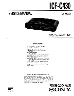
8.2 Electrical connections 

Connect the cables (mains power supply, impulse line or AFNOR output

and radio synchronisation input, depending on the model) to the

corresponding terminal strips as shown in the figure below.

(*) See page 18, the “Time outputs” menu to set this output (Pulse minute,

½ minute, second 24V or power TBT 24VDC 0,5A).

(**) depending on the SIGMA model.

RACK version: The mains power supply, impulse line and AFNOR output

and radio synchronisation input terminal strips are directly accessible at the 

rear of the Rack slide-in unit.

25

Attach the wires to each

other, near the terminal

strips.

3

C t

i

u

 cri

C

See the limit

characteristics of

these circuits on

page 28.

l

a

 nr

et

x

E

t

u

p

ni 

t

u

 pt

u

o  

F

H

D


e

r

n

½  

,

et

u

 ni

)*

(

-

9

5-

2

R

r

o ,

V

4

d

n

o

c


F

C

r

o I

-

F

t

u

p

ni 

oi

 d

ar

t

u

p

ni 

S

P

G

t

u

pt

u

r

o

nf

A

2

C t

i

u

 cri

C

(**) 110 to

230VAC or

24VDC

or

36/72VDC

1

C t

i

u

 cri

C

Summary of Contents for SIGMA H

Page 1: ...ation and start up instructions Check the product for shipping damage on reception for any reservations to the carrier B P 1 49340 TR MENTINES FRANCE T l 02 41 71 72 00 Fax 02 41 71 72 01 www bodet co...

Page 2: ...13 5 9 Version 13 6 Technician menu programming 14 6 1 Time synchronisation menu 15 6 2 Time output management menu 18 6 3 Function setting menu 20 6 4 CPU software download menu 20 6 5 Factory setti...

Page 3: ...ogram the technician functions in the order in which they appear in the menu This product must be installed in a residential commercial or light industry environment Bodet declines all responsibility...

Page 4: ...ng to NFC 15 100 for this device must include a protection of maximum 6 A n The circuit breaker must be switched off during maintenance operation Refer to labels in the product n All cables must be at...

Page 5: ...e n IMPORTANT before any installation refer to the technical characteristics paragraph n Caution n In case of replacement of the CR2032 battery it is IMPERATIVE to respect the polarity following the o...

Page 6: ...3 Description Wall box 19 Rack A LCD screen B Keypad see page 6 C Alarm indicator light red LED D Mains indicator light green LED E USB connector 6 C E B D A E B A D C...

Page 7: ...ons Keys Functions Menu key Correction key Validation key Navigation keys Note exit from the menus is automatic if a key has not been pressed for one minute in the customer menu or for 5 minutes in th...

Page 8: ...s code ok Time and date Time and date ok Dynamic radio Dynamic radio ok Language Language ok Version Version ok Choice of the time synchronisation Time output management Choice of Master or slave oper...

Page 9: ...the user menu press the menu key Enter the user access code if necessary see page 11 Access the menu options using the key and validate with The user menu options are 1 USB loading and backup 2 Add DH...

Page 10: ...When it is completed the unit displays To back up the existing Program of the Sigma Validate the option with the key The SIGMA saves the file with an automatically allocated name in the format sauve1_...

Page 11: ...ble once the receivers DHF initialized to stop this mode in this menu 5 5 Access code To enter or remove the SIGMA access code validate the option with the key The following screen is displayed Choose...

Page 12: ...time zones select PROG mode which is programmed in the technician menu PROG mode allows you to configure personalised time zone differentials and time changeovers By default it is in PROG mode The ho...

Page 13: ...d 5 8 Language To select the language of the SIGMA validate the option with the key Select the SIGMA display language from the different options available The languages available are FRENCH ENGLISH SP...

Page 14: ...then have access to the technician menu with the key The options in the technician menu are 1 Time synchro 2 Time output and DHF management impulses D1 D2 Afnor DHF and output time zone differential 3...

Page 15: ...on from an ASCII extension card NONE if you choose to have no synchronisation the radio pictogram is not displayed GPS Remark all the synchronisation options are proposed without checking that an ante...

Page 16: ...he last week The day flashes The month flashes The time flashes Validate with the key Set the start date of the summer period using the and and Validate with the key Whatever the synchronisation mode...

Page 17: ...ime base This can be useful when the master clock has no external synchronisation To access this menu you need to have selected None mode in the external synchronisation menu Set the drift using the a...

Page 18: ...ifferent options and change the values using the and keys You can go through the different outputs by validating using the key The 3 outputs Impulse 01 Afnor 02 and DHF03 are not programmable with a t...

Page 19: ...Choice of impulse length Minute 24V standard impulse length factory configuration of 1 2 seconds variable from 0 5 to 5 seconds Second 24V standard impulse length factory configuration of 0 3 seconds...

Page 20: ...t as a secondary master clock then the external input see below displays SLAVE and cannot be modified The following screen can be used to activate or deactivate the idle screen backlight by default th...

Page 21: ...install the initial factory setting To go to this SIGMA menu validate the option in the technician menu with the key The following screen is displayed To reinstall the factory configuration validate w...

Page 22: ...rmation on this alarm Example If several alarms are active simultaneously the display is Press the key to view the additional information Press the key to view the following alarms The alarms are disp...

Page 23: ...data 24V bat failure The 24V power supply is faulty check the 24V battery backup master failure The main master clock is defective control the main master clock If a Sigma SWITCH is used the stand by...

Page 24: ...crew the 2 screws on the front remove the cover for the lower cover press on the 2 clips N and slide it upwards Disconnect the flat jumpers Q be careful to connect them the same way round on reassembl...

Page 25: ...RACK version The mains power supply impulse line and AFNOR output and radio synchronisation input terminal strips are directly accessible at the rear of the Rack slide in unit 25 Attach the wires to...

Page 26: ...be protected by fuse disconnector or circuit breaker 4A maximum Indicate on the label above the terminal block the location of these protections 26 L N N D1 D2 To Bodet D1D2 movement Power supply ter...

Page 27: ...clocks DHF transmitter Time reference 927240 for master clocks SIGMA DELTA ALFA etc Note the INIT mode must be activated directly from a DIP switch on the electronic card of this transmitter not from...

Page 28: ...g 6 mm Earth terminal Rack rigid or flexible cable with end piece with cross section 1 to 1 5 Wall mounted rigid wire 1 to 1 5 bared 6 mm Other terminals Cross section 1 5 maximum bared 6 mm Electrica...

Page 29: ...ircuits 1 and 2 AFNOR coded time distribution One output standard NFS 87 500A no programming is necessary SELV l a c i n a h c e M Protection index Wall mounted IP41 Rack IP 20 Operating temperature 0...

Page 30: ...s switched on Check that the flat cable Q of the display is correctly connected on the terminal strip on the printed circuit Nothing happens when a key is pressed on the keypad It is possible that the...

Page 31: ...alidate with the key 11 2 Set the DHF output Connect the DHF transmitter to the DHF output see page 27 Switch on the SIGMA Access to the technician menu see page 14 Access to the menu Time outputs Use...

Page 32: ...5 Switch on the SIGMA Enter the technician menu see page 14 Enter the Time outputs menu Use the navigation keys to select TBT24V Caution this output is protected if the current is too high an alarm wi...

Reviews: