SECTION II: GENERAL INFORMATION
LOW WATER CUTOFF
A low water cutoff device is optional, and available for factory or field installation. For field
installation, reference the control panel figure in Section VIII (Parts List) for the location of
the device and the 24V power supply. Reference the wiring diagrams in Section IV (Installa-
tion) for proper connections. The yellow and pink wires for connection from the main control
to the low water cutoff control are labeled “LWCO.” When a low water cutoff is not present,
the yellow and pink wires are connected to close the circuit. Disconnect these wires and make
the yellow-to-yellow and pink-to-pink connections to the low water cutoff wiring harness.
BACKFLOW PREVENTER (CLOSED SYSTEM)
Some local municipal codes and ordinances require the use of these devices on potable
(domestic) water lines. Where backflow preventers, check valves, or pressure regulating valves
are required, it will be necessary to install a
thermal expansion tank
(designed for use with
potable water) in order to prevent pressure build up in the water heater and associated piping,
which could cause the T&P valve to discharge. Follow the expansion tank manufacturer’s
recommendations when selecting a tank for your hot water system. The expansion tank pressure
shall equal the water heater system pressure prior to initial warm up. Periodic relieve valve
discharges may be a result of thermal expansion in a closed water supply system. Contact the
water supplier or local plumbing inspector for information about thermal expansion tanks.
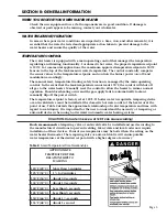
Note: Working pressure of the water heater is 150 PSI. Do not exceed 150 PSI.
CONDENSATION
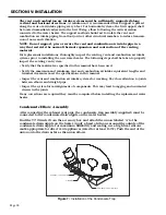
Condensation of flue gases will occur in the exhaust vent and portions of the heat exchanger
during burner operation. Condensate is considered acidic based on its typical pH range of
3.5 to 3.8 on a scale of 0 to 14 (a pH of 7 is neutral). Some installations may require the use
of a condensate neutralizer kit to reduce the acidity of the condensate prior to it entering the
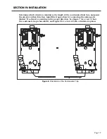
building’s drainage system. When possible, locate a floor drain in close proximity to the water
heater to minimize the length of the drain line. The water heater is supplied with a condensate
trap assembly that must be installed to the water heater before the exhaust vent is connected.
Horizontal sections of the exhaust vent shall slope upward away from the water heater a minimum
of 1/8” per foot. This will allow the condensate in the vent to run back to the condensate drain
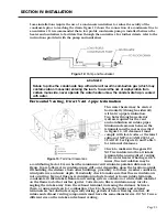
on the water heater. In some instances, condensate may form in the intake piping during periods
following burner operation. Horizontal sections of air intake piping shall slope downward away
from the water heater a minimum of 1/8” per foot. A condensate drainage tube shall be installed
on the intake piping (at the factory provided tee.)
See Section IV: Installation / Vent and Combustion Air Intake / Condensate Elbow Assembly and
Section IV: Installation / Vent & Combustion Air Intake / Intake Drain for installation details.
Page 7


