SFU-0302 SSE
M a n u a l
– 11–
BMR GmbH
2014-03-17
E
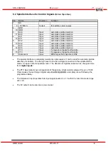
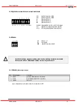
6.2 Spindle Interface for Control Signals
(D-Sub 15pin fem.)
Pin
Name
Direction
Function
1 NC
9 +5V/50mA
Output
for auxiliary power supply
2 GND
10 GND
3
Bit 0
Input
automatic spindle detection
11 Bit 0
Input
automatic spindle detection
4
Bit 1
Input
automatic spindle detection
12 Bit 1
Input
automatic spindle detection
5
Bit 2
Input
automatic spindle detection
13 Bit 2
Input
automatic spindle detection
6
Bit 3
Input
automatic spindle detection
14 Bit 3
Input
automatic spindle detection
7
PTC
Input
Temperature Signal from Spindle
15 PTC
Input
Temperature Signal from Spindle
8
Hall sensor
Input
RPM-Signal from Spindle to DSP
•
The spindle interface is completely isolated by optocouplers. It can be used for automatic spindle
detection, if enabled.. To set a high level to one bit, a simple connection to the spindle GND is
made. An open contact equals low level. The direction of high/low active can be changed in the
form ‘digital inputs’.
•
The PTC input detects over-temperature of the spindle. A high resistor value at this pin of >600
Ohms causes the switching of digital output overtemp spindle and safety cut-out following the
programmed delay .
•
The Hall sensor input operates from input signal levels of +/- 1V within the common mode range
of 0..10V.
•
The 5V output can be used as a power suppl.
Summary of Contents for SFU-0302-SSE
Page 1: ...Frequency Converter SFU 0302 SSE ...
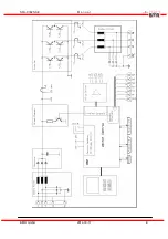
Page 5: ...SFU 0302 SSE M a n u a l 5 BMR GmbH 2014 03 17 E 3 Block Diagram ...
Page 6: ...SFU 0302 SSE M a n u a l 6 BMR GmbH 2014 03 17 E ...
Page 28: ...SFU 0302 SSE M a n u a l 28 BMR GmbH 2014 03 17 E 13 Mechanics Views Dimensions ...
Page 29: ...SFU 0302 SSE M a n u a l 29 BMR GmbH 2014 03 17 E this page is left intentionally left blank ...


