


Hardware Installation
Installation and initialization of the BlueField BF1600 Controller Card require attention to the mechanical, power, and precautions for rack-mounted
equipment.
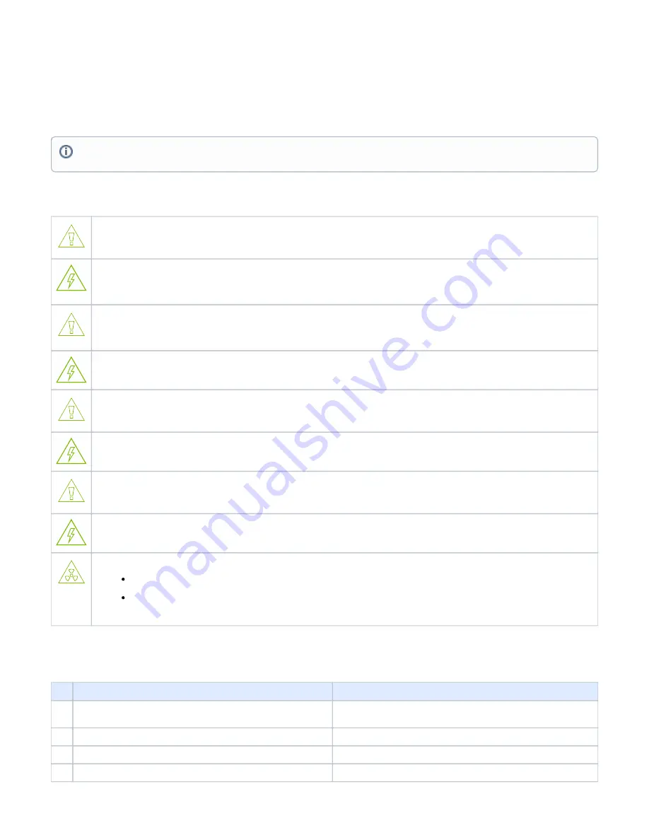
Safety Warnings
Please observe all safety warnings to avoid injury and prevent damage to system components. Note that not all warnings are relevant to all models.
Note that not all warnings are relevant to all models.
General Installation Instructions
Read all installation instructions before connecting the equipment to the power source.
Jewelry Removal Warning
Before you install or remove equipment that is connected to power lines, remove jewelry such as bracelets, necklaces, rings, watches, and
so on. Metal objects heat up when connected to power and ground and can meltdown, causing serious burns and/or welding the metal
object to the terminals.
Over-temperature
This equipment should not be operated in an area with an ambient temperature exceed-ing the maximum recommended: 55°C (131°F). An
airflow of 200LFM at this maximum ambient temperature is required for HCA cards and NICs. To guarantee proper airflow, allow at least
8cm (3 inches) of clearance around the ventila-tion openings.
During Lightning - Electrical Hazard
During periods of lightning activity, do not work on the equipment or connect or dis-connect cables.
Copper Cable Connecting/Disconnecting
Some copper cables are heavy and not flexible, as such, they should be carefully attached to or detached from the connectors. Refer to the
cable manufacturer for spe-cial warnings and instructions.
Equipment Installation
This equipment should be installed, replaced, or serviced only by trained and qualified personnel.
Equipment Disposal
The disposal of this equipment should be in accordance to all national laws and regula-tions.
Local and National Electrical Codes
This equipment should be installed in compliance with local and national electrical codes.
Hazardous Radiation Exposure
Caution – Use of controls or adjustment or performance of procedures other than those specified herein may result in hazardous
radiation exposure.For products with optical ports.
CLASS 1 LASER PRODUCT and reference to the most recent laser standards:
IEC 60 825-1:1993 + A1:1997 + A2:2001 and EN 60825-1:1994+A1:1996+ A2:20
Installation Procedure Overview
The installation procedure of BlueField Controller Card involves the following steps:
Step
Procedure
Direct Link
1
Unpack the package and confirm that you have received all the
required components
Refer to
2
Check the system’s hardware and software requirements.
Refer to
3
Pay attention to the air flow consideration within the JBOF system
Refer to
AirFlow Requirements
4
Follow the pre-installation check list
Refer to
Safety warnings are provided here in the English language. For safety warnings in other languages, refer to the
document available on
.


