background image

Need help? 1.800.762.1142

Do not return to place of purchase.

Recipes

BlueRhino.com/recipes

Replacement Parts

parts.BlueRhino.com

1.800.762.1142

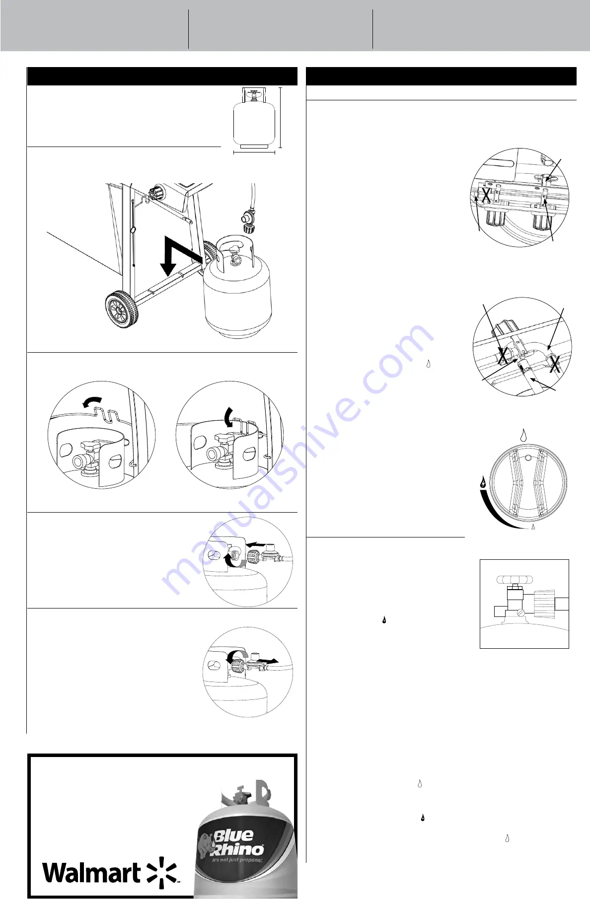
Installing LP Gas Tank

To operate, you will need one precision-filled standard grill LP gas 
tank with external valve threads .


W

CAUTION: LP gas tank must be properly 

disconnected and removed prior to moving this 

grill.

Inserting LP Gas Tank

Place precision-filled LP gas tank upright into the notches in the right cart frame so the tank 
valve is facing the gas line connection .

Securing LP Gas Tank

Secure tank by sliding the tank retainer wire over shoulder of LP gas tank .

Connecting LP Gas Tank

1 .  Before connecting, be sure there is no debris caught 

in the head of the LP gas tank, head of the regulator 
valve or in the head of the burner or burner ports .     

2 .   Connect regulator/hose assembly to tank by turning 

knob clockwise until it stops . 

Disconnecting LP Gas Tank

1 .  Before disconnecting, make sure the LP gas tank valve 

is “CLOSED .”

2 .  Disconnect regulator/hose assembly from LP gas tank 

by turning knob counterclockwise until it is loose .


W

CAUTION: LP gas tank must be properly 

disconnected and removed prior to 

moving this grill.

3 .  Place the protective cap cover on the LP tank and 

store the tank outdoors in a well ventilated area out of 
direct sunlight .

20 lb

9 Kg

17.9 in.

 / 45.5 cm

12.2 in. / 31 cm

Operating Instructions

Checking for Leaks

Burner Connections

1 .  Make sure the regulator hose and valve 

connections are securely fastened to the burner 
and the tank .  

2 .  Visually check the connection between the 

burner/venturi tube and orifice . 

3 .  Make sure the burner/venturi tube fits over the 

orifice . 


W

WARNING: Failure to inspect this 

connection or follow these instructions 

could cause a fire or an explosion 

which can cause death, serious bodily 

injury or damage to property.   

4 .  Please refer to diagram for proper installation  

(Figures 1 and 2) .

5 .  If the burner/venturi tube does not rest flush to the 

orifice, as shown, please contact 1 .800 .762 .1142 
for assistance .

Tank/Gas Line Connection

1 .  Make 2-3 oz . of leak detection solution by mixing 

one part liquid dishwashing soap with three parts 
water .  

2 .  Make sure control knobs are in the “  OFF” 

position (Figure 3) .

3 .  Connect LP gas tank per “Installing LP Gas Tank” 

section .

4 .  Turn LP gas tank valve to “OPEN .”
5 .  Spoon several drops of solution, or use a squirt 

bottle, at all “X” locations (Figures 1, 2 and 4) .
a . If any bubbles appear, turn LP gas tank valve to 

“CLOSED,” reconnect and re-test . 

b . If you continue to see bubbles after several 

attempts, turn LP gas tank valve to “CLOSED” 
and disconnect LP gas tank, per “Disconnecting 
LP Gas Tank” section . Contact 1 .800 .762 .1142 
for assistance .

c . If no bubbles appear after one minute, turn 

LP gas tank valve to “CLOSED,” wipe away 
solution and proceed .

Operating Main Burners

First Use 

1 .  Make sure all labels, packaging and protective 

films have been removed from the grill . 

2 .  Remove manufacturing oils before cooking on this 

grill for the first time by operating the grill for at 
least 15 minutes on   (HIGH) with the lid closed . 
This will “heat clean” the internal parts and 
dissipate odors . 

Lighting


W

CAUTION: Keep outdoor gas cooking appliance area clear and free 

from combustible materials, gasoline and other flammable vapors and 

liquids.


W

CAUTION: Do NOT obstruct the flow of combustion and ventilation air.


W

CAUTION: Check and clean burner/venturi tubes for insects and insect 

nests. A clogged tube can lead to a fire.


W

CAUTION: Attempting to light the burner with the lid closed may cause 

an explosion.

1 .  Open lid . 
2 .  Check for obstructions of airflow to the burners . Spiders, insects and webs can clog the 

burner/venturi tube .  A clogged burner tube can lead to a fire .

3 .  All control knobs must be in the “  OFF” position (Figure 3) .
4 .  Connect LP gas tank per “Installing LP Gas Tank” section .
5 .  Turn LP gas tank valve to “OPEN .”
6 .  Push and turn any control knob to   (HIGH) . The burner should light . If it does not, repeat 

up to three times .

7 .  If ignition does not occur in 5 seconds, turn burner control knob “  OFF,” wait 5 minutes, 

and repeat lighting procedure .  

Figure 1: Main Burners

Burner/
Venturi Tube

LP Gas 
Valve with 
Orifice

LP Gas 
Connection

Figure 2: Side Burner

LP Gas 
Connection

Valve Soft Pipe 
Connection

LP Gas 
Valve with 
Orifice

Burner/
Venturi 
Tube

Figure 3

OFF

APAGADO

Figure 4

X

X

X

X

X

Available at:

Need 

Propane?

Summary of Contents for GBC1429WB

Page 1: ...ause cancer birth defects or other reproductive harm Made from 75 Bagasse environmentally friendly sugar cane pulp by product WARNING FOR YOUR SAFETY For Outdoor Use Only outside any enclosure WARNING FOR YOUR SAFETY 1 Improper installation adjustment alteration service or maintenance can cause injury or property damage 2 Read the installation operation and maintenance instructions thoroughly befo...

Page 2: ...rned off at the supply cylinder and disconnected W W Do NOT store a spare LP gas cylinder under or near this appliance W W Never fill the cylinder beyond 80 percent full W W A fire causing serious injury or damage to property may occur if the above is not followed exactly W W Never attempt to attach this grill to the self contained LP gas system of a camper trailer motor home or house W W Never us...

Page 3: ...perly disconnected and removed prior to moving this grill W W Storage of grill indoors is permissible only if the cylinder is disconnected removed from the grill and properly stored outdoors W W Always open grill lid carefully and slowly as heat and steam trapped within grill can cause severe burns W W Do NOT attempt to disconnect the gas regulator from the cylinder or any gas fitting while the gr...

Page 4: ...Support 55 07 316 20 Grease Cup 55 07 315 21 Right Side Shelf 55 24 796 22 Left Cart Frame 55 24 797 23 Cart Frame Support A 55 23 007 24 LP Gas Tank Retainer Wire 55 23 011 25 Right Cart Frame 55 24 798 26 Lighting Rod 55 10 056 27 Cart Frame Support B 55 23 008 28 Foot 2 55 23 012 29 Wheel 2 55 07 363 30 Front Panel 55 25 189 31 Axle 55 24 800 Pre assembled Expanded View Hardware A Screw M4x10 N...

Page 5: ...e that s free of cracks or openings 2 Spread out all parts 3 Tighten all hardware connections by hand first Then before completing each step go back and fully tighten all hardware Be careful not to over tighten That could damage surfaces or strip threads 4 For best results complete each step in the order presented To complete assembly you will need 1 Leak detection solution instructions on how to ...

Page 6: ...Assembly Instructions continued 6 Attach Axle Wheels and LP Gas Tank Retainer Wire I x 1 7 Attach Lid Handle Heat Plate Handle and Temperature Gauge E x 2 G x 2 H x 2 8 Attach Grill Body Assembly B x 6 F x 6 H x 6 5 Attach Cart Frame Supports A B B x 2 D x 1 ...

Page 7: ...ipes Replacement Parts parts BlueRhino com 1 800 762 1142 7 9 Attach Tool Hook B x 2 10 Attach Left Side Shelf Note Leave 5 mm of bolt threads exposed C x 4 11 Attach Right Side Shelf Note Leave 5 mm of bolt threads exposed C x 4 12 Attach Control Knob Bezel and Side Burner Valve A x 2 ...

Page 8: ...No WM16 GBC1429WB 8 Assembly Instructions continued 15 Attach Warming Rack and Control Knobs 16 Insert Grease Cup Support and Grease Cup 14 Insert Heat Plates and Cooking Grid 13 Insert Side Burner Igniter Wire and Side Burner Grid A x 2 ...

Page 9: ...tection solution by mixing one part liquid dishwashing soap with three parts water 2 Make sure control knobs are in the OFF position Figure 3 3 Connect LP gas tank per Installing LP Gas Tank section 4 Turn LP gas tank valve to OPEN 5 Spoon several drops of solution or use a squirt bottle at all X locations Figures 1 2 and 4 a If any bubbles appear turn LP gas tank valve to CLOSED reconnect and re ...

Page 10: ...ndently repeat steps 5 9 for the other burners W W CAUTION If burner flame goes out during operation immediately turn the control knobs to the OFF position LP gas tank valve CLOSED and open lid to let the gas clear for 5 minutes before re lighting Turning Off 1 Turn LP gas tank valve to CLOSED 2 Turn all control knobs clockwise to the OFF position Note A poof sound is normal as the last of the LP ...

Page 11: ...lobal Sourcing Inc Blue Rhino warrants to the original retail purchaser of this product and to no other person that if this product is assembled maintained and operated in accordance with the printed instructions accompanying it then for a period of five 5 years for the burners and one 1 year for all remaining parts from the date of purchase all parts in such product shall be free from defects in ...

Page 12: ...ts Sudden drop in gas flow or reduced flame height Out of gas Exchange refill or replace LP gas tank Overfilling prevention device may have been activated 1 Turn control knobs to OFF 2 Wait 30 seconds and light grill 3 If flames are still too low reset the overfilling prevention device a Turn control knob s OFF b Turn LP gas tank valve to CLOSED c Disconnect regulator d Turn control knobs to HIGH ...

Page 13: ...Need help 1 800 762 1142 Do not return to place of purchase Recipes BlueRhino com recipes Replacement Parts parts BlueRhino com 1 800 762 1142 13 ...

Page 14: ...Outdoor LP Gas Barbecue Grill Model No WM16 GBC1429WB 14 ...

Page 15: ...uidos o vapores inflamables cerca de esta unidad o de cualquier otro aparato 2 Un tanque de propano líquido que no esté conectado para su uso no se debe almacenar cerca de éste o cualquier otro aparato PELIGRO Nunca deje este artefacto encendido sin vigilancia Índice Salvaguardias importantes Página 2 Despiece y elementos de ferretería 4 Instrucciones de armado 5 Instalación del tanque de gas prop...

Page 16: ...ves o la muerte W W NO obstruya los agujeros situados a los lados y en la parte trasera de la parrilla W W NO ponga nunca un tanque de gas propano lleno en un carro o camioneta calientes El calor podría hacer que la presión del gas aumentase lo que abriría la válvula de seguridad y haría que se escapase el gas W W Ponga la tapa contra el polvo en la válvula de salida del tanque cuando no lo esté u...

Page 17: ...ar o quemar residuos de alimentos con la perilla en la graduación más alta Si la parrilla no ha sido limpiada puede incendiarse la grasa y dañar el producto W W NO coloque los recipientes de cocción sobre el artefacto mientras está en funcionamiento W W Tenga cuidado al colocar cosas sobre la parrilla cuando ésta se encuentre en funcionamiento W W NO intente mover la parrilla mientras esté encendi...

Page 18: ...nija de la tapa 55 23 618 4 Tapa 55 25 188 5 Placa de distribución de calor 3 55 22 094 6 Rejilla de calentamiento 55 10 116 7 Bisagra superior 2 55 09 147 8 Bisagra inferior 2 55 09 117 9 Quemador 3 55 23 003 10 Ganchos porta utensilios 55 11 279 11 Repisa izquierda 55 23 004 12 Rejilla de cocción 55 23 001 13 Carcasa de la parrilla 55 23 005 14 Rejilla del quemador lateral 55 10 047 15 Soporte d...

Page 19: ...s ni hendijas 2 Presente todas las piezas 3 Ajuste todas las conexiones de los elementos de ferretería primero en forma manual Luego después de completar cada paso ajústelos por completo Tenga cuidado de no ajustar demasiado Se podrían dañar las superficies o forzar las roscas 4 Para obtener mejores resultados siga todos los pasos en el orden indicado Para terminar el armado de la unidad necesitar...

Page 20: ... el eje las ruedas y el alambre de retención del tanque de propano I x 1 7 Acople el protector contra el calor de la manija de la tapa la manija y el indicador de temperatura de la tapa E x 2 G x 2 H x 2 8 Acople la carcasa de la parrilla B x 6 F x 6 H x 6 5 Acople las varas de soporte A y B del carro B x 2 D x 1 ...

Page 21: ...ino com 1 800 762 1142 7 9 Acople los ganchos porta utensilios B x 2 10 Acople la repisa izquierda Nota Deje expuesto un segmento de la rosca del perno de unos 5 mm C x 4 11 Acople la repisa derecha Nota Deje expuesto un segmento de la rosca del perno de unos 5 mm C x 4 12 Acople el soporte de la perilla de control y la válvula del quemador lateral A x 2 ...

Page 22: ...ón 15 Coloque la rejilla de calentamiento y las perillas de control 16 Inserte el soporte del recogedor de grasa y el recogedor de grasa 14 Coloque las placas de distribución de calor y la rejilla de cocción 13 Acople el quemador lateral el alambre del encendedor y la rejilla del quemador lateral A x 2 ...

Page 23: ...illa por lo menos por 15 minutos en la graduación alto con la tapa cerrada Esto realizará una limpieza por calor en las piezas internas de la unidad y hará que los olores se disipen Encendido W W PRECAUCIÓN Mantenga el área del aparato de cocción para exteriores limpia y libre de materiales combustibles gasolina y otros líquidos y vapores inflamables W W PRECAUCIÓN No obstruya el flujo del aire de...

Page 24: ...idos dentro y obstruir los orificios del quemador tubo de venturi Un tubo de quemador obstruido puede provocar un incendio debajo del aparato 3 Todas las perillas tienen que estar en la posición APAGADO Vea la Figura 3 4 Conecte el tanque de gas propano líquido siguiendo las instrucciones descritas en la sección Instalar el tanque de gas propano líquido 5 Coloque la válvula del tanque de gas propa...

Page 25: ...arranty o llamando al 1 800 762 1142 Piezas de repuesto Puede encontrar piezas de repuesto en parts BlueRhino com o llame al 1 800 762 1142 Limpieza y cuidado W W PRECAUCIÓN 1 Todas la operaciones de limpieza y mantenimiento deben realizarse con la parrilla fría y con el tanque de propano desconectado 2 NO limpie ninguna pieza de esta parrilla en un horno de limpieza automática El calor extremo da...

Page 26: ...omo se prescribe en este manual del usuario Además la garantía limitada no cubre daños al terminado de la unidad tales como rasguños abolladuras descoloridos oxidaciones y otros daños causados por la intemperie después de la compra de la unidad Esta garantía limitada reemplaza cualquier otra garantía Blue Rhino no asume ninguna responsabilidad por garantías de productos vendidos por quienes no sea...

Page 27: ...no sin utilizar ninguna herramienta Obstrucción del flujo de gas 1 Limpie los tubos del quemador 2 Verifique que la manguera no esté torcida o doblada Desacoplamiento del quemador a la válvula Vuelva a conectar el quemador y la válvula Telarañas o nidos de insectos en el venturi Limpie el tubo de venturi y el tubo del quemador Orificios del quemador atascados u obstruidos Limpie las bocas del quem...

Page 28: ...ma 4 Una vez se haya enfriado la parrilla quite y limpie todas las piezas siguiendo las instrucciones de Limpieza y cuidado del manual del usuario Centelleos hay fuego en el los tubo s del quemador El quemador y o juegos de quemadores están bloqueados Limpie el quemador y o el los tubo s del quemador El interior de la tapa se está pelando igual que cuando se pela la pintura La acumulación de grasa...

Reviews: