background image

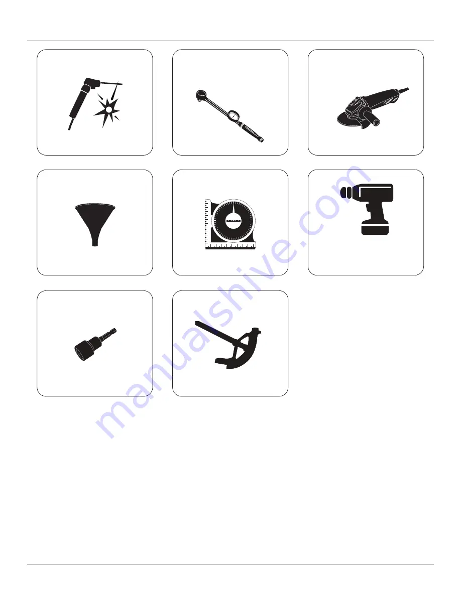
 Welder

Torque Wrench


Grinder with Zip Blades As Well 

 Funnel

 Angle Measurement Tool

Drill/Screwdriver

 Nut Driver Drill Bit 5/16”

Conduit Bender 

STRONGARM™ RVR303 VEHICLE RESTRAINT — INSTALLATION & TECHNICAL MANUAL

17

ISSUE DATE: OCTOBER 26, 2021 REV. 1.0 (PART # 038-953EI)

Summary of Contents for STRONGARM RVR303

Page 1: ...REV 1 0 PART 038 953EI STRONGARM RVR303 VEHICLE RESTRAINT WITH BLUE GENIUS TOUCH CONTROL INSTALLATION TECHNICAL MANUAL WARNING Do not operate or service this product unless you have read and fully understand the entire contents of this manual Failure to do so may result in property damage bodily injury or death ...

Page 2: ......

Page 3: ... 23 9 5 HOIST CYLINDER ASSEMBLIES OPTIONAL 23 10 0 CONTROL STATION INSTALLATION 26 10 0 CONTROL STATION INSTALLATION 26 10 1 POWERPACK HARDWARE INSTALLATION 26 10 1 POWERPACK HARDWARE INSTALLATION 26 10 2 ELECTRICAL CONDUIT INSTALLATION 28 10 2 ELECTRICAL CONDUIT INSTALLATION 28 10 3 REMOTE I O JUNCTION INSTALLATION 29 10 3 REMOTE I O JUNCTION INSTALLATION 29 10 4 POWERPACK ELECTRICAL INSTALLATION...

Page 4: ...L MANUAL 4 ISSUE DATE OCTOBER 26 2021 REV 1 0 PART 038 953EI 13 0 TROUBLESHOOTING 43 13 0 TROUBLESHOOTING 43 13 1 VEHICLE RESTRAINT TROUBLESHOOTING 43 13 1 VEHICLE RESTRAINT TROUBLESHOOTING 43 13 2 BLUE GENIUS LCD MESSAGES 43 13 2 BLUE GENIUS LCD MESSAGES 43 ...

Page 5: ... AS SHIPPED CHECKLIST on page 20 F F 7 Do you have all the tools needed to complete the job This includes ladder s safety equipment and personal safety devices See 6 0 TOOLS REQUIRED FOR INSTALLATION on page 16 F F 8 Do you have all the anchors for the exterior driver traffic light warning sign and control box Supplied by You contractor installer F F 9 Have you read this installation manual and fu...

Page 6: ...member of Loading Dock Equipment Manufacturers A Product Section of Material Handling Industry of America A Division of Material Handling Industry 8720 Red Oak Blvd Suite 201 Charlotte NC 28217 3992 Telephone 704 676 1190 www mhi org lodem 2 1 2 1 WARRANTY INFORMATION WARRANTY INFORMATION Thank you for purchasing Blue Giant products We appreciate your business and are confident that our product wi...

Page 7: ...receipt for transport damage Any observed transport damage is to be listed on the signed copy of the freight document Notify the freight forwarder and the dealer of any damage WITHIN 24 HOURS 2 4 2 4 INSTALLER S GUIDELINES INSTALLER S GUIDELINES Please read all instructions carefully before installing this Blue Giant dock product Proper installation of this product is required to ensure safe opera...

Page 8: ...rt of a procedure or hardware warning decal DANGER BEFORE BEGINNING ANY SERVICE PROCEDURES Disconnect the power and follow all lockout tagout procedures Installation must be performed only by trained and authorized personnel Prior to installation place adequate barriers to prevent vehicle traffic from entering the work area Any electrical work must be performed by qualified personnel only Do not r...

Page 9: ...t ground welding equipment to any electrical components Do not allow the drill to go too deeply when drilling holes in the control box Damage to the control systems may occur Never use air to blow debris from control box Use a vacuum to remove debris from control box Do not connect green ground lead into control box until all welding has been completed Check hydraulic fluid level Improper adjustme...

Page 10: ...n the OFF position or disconnected from the energy source Blue Giant strongly recommends that only OSHA approved and or local jurisdiction lockout devices and procedures be utilized The energy isolating device must bear a prominent warning tag indicating that work is being done on the equipment and the name of the authorized employee responsible for the lockout It is mandatory that tagout notices ...

Page 11: ...ever be handed to other personnel or set down anywhere 3 Place PCBs in black ESD shielding bags for return or storage Only one PCB or sensor should be placed in a static bag Attach paperwork and other items to the outside with adhesive pouches or elastic bands 4 The control boxes protect the PCBs inside from static and should not be used to store manuals or other accessories ATTENTION DO NOT DISCA...

Page 12: ...trade size conduit through the pit floor for the Communication and Hydraulic lines from the hydraulic Powerpack to the RVR303 conduit knockout 5 Wire the lip sensor See Section 11 2 WIRING DIAGRAMS on page 38 for more information MINIMUM CONCRETE STRENGTH 3 000 P S I INSIDE BUILDING VIEW 66 typ 1676 mm TRAFFIC LIGHT mounted wired by others BLUE GENIUS mounted wired by others PIT MOUNT POWERPACK 20...

Page 13: ...or to the pit wall 5 Wire the lip sensor See Section 11 2 WIRING DIAGRAMS on page 38 for more information MINIMUM CONCRETE STRENGTH 3 000 P S I INSIDE BUILDING VIEW TRAFFIC LIGHT mounted wired by others 84 2134 mm 66 typ 1676 mm BLUE GENIUS mounted wired by others REMOTE I O J BOX REMOTE POWERPACK 20 508 mm 4 102 mm Dock Home Dock interlock sensor to Remote I O 66 typ 1676 mm 84 typ 2134 mm MAIN P...

Page 14: ... for the lip sensor to the pit wall 5 Wire the lip sensor See Section 11 2 WIRING DIAGRAMS on page 38 for more information MINIMUM CONCRETE STRENGTH 3 000 P S I INSIDE BUILDING VIEW 20 508 mm 4 102 mm 84 2134 mm 66 typ 1676 mm TRAFFIC LIGHT mounted wired by others BLUE GENIUS mounted wired by others REMOTE POWERPACK REMOTE I O J BOX Dock Home Dock interlock sensor to Remote I O MAIN POWER from fus...

Page 15: ...E EXTERIOR DRIVER TRAFFIC LIGHT on page 32 and 10 9 INSTALLING THE EXTERIOR DRIVER WARNING SIGN on page 33 ELECTRICAL REQUIREMENTS 1 Mount control station to wall 2 Fused disconnect provided by others and wiring by others 3 Install wiring from control station to hydraulic Powerpack 4 Install wiring from Powerpack to power supply 48 1219 mm Dock Height TYP 105 2667 mm Sign TYP 84 2134 mm Light TYP ...

Page 16: ... Combination wrench set 3 8 to 1 5 8 and Concrete Bit Carbide 2 Level Socket Set 3 8 to 1 Blow out Pump Concrete Dust Ball Peen Hammer Small Flat Screwdriver flat tip to be suitable for 150 slot Large 1 8 x 3 8 Screwdriver Electrician s Tools Welder Sledge Hammer 10 lb STRONGARM RVR303 VEHICLE RESTRAINT INSTALLATION TECHNICAL MANUAL 16 ISSUE DATE OCTOBER 26 2021 REV 1 0 PART 038 953EI ...

Page 17: ...with Zip Blades As Well Funnel Angle Measurement Tool Drill Screwdriver Nut Driver Drill Bit 5 16 Conduit Bender STRONGARM RVR303 VEHICLE RESTRAINT INSTALLATION TECHNICAL MANUAL 17 ISSUE DATE OCTOBER 26 2021 REV 1 0 PART 038 953EI ...

Page 18: ...t is recommended for the safe hoisting of the RVR303 restraint into a pit All necessary regulatory rules must be followed for safe handling of the dock lift Sling and Hoist Ring Forklift Boom Truck STRONGARM RVR303 VEHICLE RESTRAINT INSTALLATION TECHNICAL MANUAL 18 ISSUE DATE OCTOBER 26 2021 REV 1 0 PART 038 953EI ...

Page 19: ...ncrete could result in death or serious injury Inadequate lifting equipment or practices can cause a load to fall unexpectedly Make sure the lifting chain or other lifting devices are in good condition and have a rated capacity of as much as 5000 lb 2268 kg for the lifting angle used Failure to follow this warning can allow the dock equipment to fall tip or swing into people causing death or serio...

Page 20: ...read Arm Blocked Consult the Troubleshooting section of the manual MENU DISPLAY SCREEN VEHICLE RESTRAINT OVERRIDE 1 Touch the Engage button If a vehicle s ICC bar is absent or cannot be engaged the LCD screen will read ICC Bar Not in Range A visual inspection is now necessary to determine whether the vehicle needs to be realigned or if wheel chocks are necessary The control panel light and traႈc l...

Page 21: ...nish 1 032 806 Exterior Traffic Light 1 3 lbs 0 6 kg 1 028 206 Lip Sensor 0 4 lbs 0 18 kg 1 21 002154 Mounting Bracket C 1 038 225 E Exterior Driver Warning Sign English French Spanish 0 7 lbs 0 32 kg F S D 2 1001730 Retainer Assembly 1 5 lbs 0 45 kg E 1 1002880 PowerPack See section for Voltages 90 9 lbs 41 2 kg 1 038 538 Breather Cap with Dipstick 5 lbs 22 kg STRONGARM RVR303 VEHICLE RESTRAINT I...

Page 22: ...e procedures WARNING Always lockout and tagout any power source before performing any work on any electrical devices or electrical controls according to OSHA regulations and approved local electrical codes 1 Carefully sling the lift into position Follow local regulation requirements for hoisting 2 Lower restraint weldment body into position as per drawings centered or off centered 3 Measure the re...

Page 23: ...BLIES OPTIONAL HOIST CYLINDER ASSEMBLIES OPTIONAL If the weldment body was shipped and mounted without the cylinder assemblies inside then a hoist is required to correctly install the hydraulic cylinders DANGER Follow local regulation requirements for hoisting Do not work stand near or put any part of your body under any hoisted object restraint or dock equipment Do not leave any load on the lift ...

Page 24: ...he hook cylinder does As the hook cylinder enters its trunnion the tilt cylinder will move into its normal operating position 6 Apply Blue LOCTITE 242 to the necessary bolts then bolt the hook cylinder and tilt cylinder into place on their trunnion carriages 7 Place the sensor bracket on left side to face the wand STRONGARM RVR303 VEHICLE RESTRAINT INSTALLATION TECHNICAL MANUAL 24 ISSUE DATE OCTOB...

Page 25: ...the RVR303 Powerpack 9 Install the J box on the right side wall with the pre installed screws and rubber inserts are provided STRONGARM RVR303 VEHICLE RESTRAINT INSTALLATION TECHNICAL MANUAL 25 ISSUE DATE OCTOBER 26 2021 REV 1 0 PART 038 953EI ...

Page 26: ...pack 3 Install oil dip stick in tank and verify oil level 4 Remove temporary plugs from breather and vent line fittings located side by side on top surface of reservoir Breather fitting is 1 2 12mm NPT and vent line fitting is 1 4 6mm NPT 5 Locate and remove plastic cap plug from hydraulic hose connector fitting on the power pack 6 Position and permanently attach hydraulic hose reservoir breather ...

Page 27: ...at surface If the wall is uneven shim to suit Verify that the control station power rating is compatible with that of the power supply All wiring inside the control station must be neatly laid out avoid crossovers and untidy excessive wiring patterns All wiring must be completed in accordance with national and local codes Use 12 gauge stranded wired for motor and power leads only A local disconnec...

Page 28: ...he control station to the traffic lights for the light s power cable 2 Run 13 mm conduit from the control station to the vehicle restraint s remote motor 3 Run 13 mm conduit from the control station to the vehicle restraint s remote motor I O controller 4 Run 13 mm conduit from the I O box to the vehicle restraint s IPS sensor 5 Verify that all fasteners have been tightened and secured NOTE Instal...

Page 29: ...IPS communication wire and the wire for the lip home sensor will need to be connected See Section 11 2 WIRING DIAGRAMS on page 38 for proper connections Callouts Description A Communication cable to control station B Communication cable to vehicle restraint IPS C Control cable to lip home sensor D to Hydraulic Solenoids E Anchor Point NOTE Cover removed for clarity C B A D E STRONGARM RVR303 VEHIC...

Page 30: ...ge any two motor leads If the powerpack s location prevents a visual inspection of the motor to determine the direction of rotation 1 Complete mechanical installation and electrical hook up as required 2 Turn power supply ON 3 Observe unit and run power pack motor by operating UP push button for no more than 5 seconds 4 If unit begins to raise rotation is correct 5 If there is no indication of mov...

Page 31: ...delay between the button being touched and the arm rising air is present in the system and will need to be bled out 10 6 10 6 HYDRAULIC AIR BLEEDING HYDRAULIC AIR BLEEDING The RVR303 is shipped with hydraulic oil in the pre installed hoses Remove the plugs from the hoses only when attaching them to the powerpack If appropriate care is exercised bleeding should not be necessary But should a situati...

Page 32: ...quare and level Add shims to the back if needed Do not over tighten the fasteners When drilling the hole for the cable ensure that the hole is thoroughly deburred cleaned out so that accidental damage does not occur when the cable is pulled through during and after installation 9 3 8 238 mm 10 254 mm 5 127 mm 4 3 8 111 mm Ø 5 16 21mm x 4 Exterior driver traffic light part 032 806 NOTE Mount to a f...

Page 33: ... for expansion reasons i e for a 1 4 anchor use a 5 16 hole When mounting the sign do a visual inspection to confirm that it is level and centered beneath the traffic light When fastening the sign to the wall make sure that the sign does not warp or twist as a result of tightening the anchors Use shim washer if needed Do not over tighten fastenings as damage to the sign may occur Exterior driver w...

Page 34: ...t it is tight against the night locks and resting on the C channel Ensure that the guide is positioned close to the dock interlock sensor 1 Mount the sensor bracket with a C clamp 2 Positioning the bracket the sensor should be inserted halfway inside the bracket hole This will allow for easy adjustment of the sensor either closer or further to the back of the lip 3 With the sensor in place test th...

Page 35: ...to the sensor and torque both nuts to 40 ft lb 8 Adjust the lip stop to ensure that the lip does not come into contact with the sensor but also rests firmly in the lip keepers Typically a 25 6mm gap between lip and proximity sensor is required 9 Clean up the entire work area and apply touch up paint to all welds scratches and burns 10 11 10 11 SENSOR RANGE ADJUSTMENT SENSOR RANGE ADJUSTMENT Sensor...

Page 36: ...w down terminal connections are inserted and tightened in place If stranded wire is used ensure that no loose strands remain NOTE Note that MC for Motor 1 and MC for Motor 2 are internally connected 7 Wiring should be neatly performed excessive and untidy arrangements can cause noise interference 8 The configuration viewed from left to right on the bottom of the Blue Genius control station must be...

Page 37: ...tage away from high voltage within the Blue Genius control station 11 1 11 1 BLUE GENIUS CONTROL STATION WIRING LAYOUT BLUE GENIUS CONTROL STATION WIRING LAYOUT NOTICE Follow the Wiring Diagram provided with the control panel please leave the original with the control panel Standalone wiring diagram is provided in Section for reference without being at site with equipment Use illustration for typi...

Page 38: ...d Mississauga ON L5T 2N6 6350 Burnt Poplar Road Greensboro NC 27409 800 872 2583 Fax 905 457 2313 www bluegiant com info bluegiant com WHITE GREEN BLACK RED BLACK RED AUDIBLE ALARM WHITE GREEN RED BLACK DRAIN 24 COM DRAIN DRAIN Twist Insulate 03 04 01 02 DOOR CONTROL OPT A B 03 04 01 02 A B COM 24 07 08 05 06 OUTPUT 1 24 OUTPUT 2 24 11 12 09 10 OUTPUT 3 24 OUTPUT 4 24 15 16 13 14 OUTPUT 5 24 OUTPU...

Page 39: ... BLACK RED AUDIBLE ALARM WHITE GREEN RED BLACK DRAIN 24 COM DRAIN DRAIN Twist Insulate 03 04 01 02 DOOR CONTROL OPT A B 03 04 01 02 A B COM 24 07 08 05 06 OUTPUT 1 24 OUTPUT 2 24 11 12 09 10 OUTPUT 3 24 OUTPUT 4 24 15 16 13 14 OUTPUT 5 24 OUTPUT 6 24 17 18 19 20 21 22 23 24 25 26 27 28 29 30 31 32 33 34 COM COM COM COM INPUT 1 INPUT 2 INPUT 3 COM COM 24 24 24 24 INPUT 4 INPUT 5 24 24 INPUT 6 GROUN...

Page 40: ...red and closed F Is there any sign of an oil leak F Was the hydraulic hose connected and routed properly F Is the breather hose attached to the top of each cylinder F Is the powerpack electrically connected to the nameplate voltage F Is the breather hose from the powerpack present and installed correctly F Is the wiring diagram inside the control panel F Are the cylinders in their mounts properly ...

Page 41: ...een Do Not Enter Proceed With Caution www BlueGiant com Gold Series TM DISCONNECT POWER BEFORE OPENING READ AND FULLY UNDERSTAND THE OWNER S MANUAL BEFORE OPERATING THIS PRODUCT WARNING R 038 244E STOP R E S T R A I N T 0 ESC SEL 8 9 5 6 2 3 1 4 7 Enter On Gr een Do Not Enter Proceed With Caution www BlueGiant com Gold Series DISCONNECT POWER BEFORE OPENING READ AND FULLY UNDERSTAND THE OWNER S MA...

Page 42: ...he arm will return to the 90 degree position then the LCD messages will follow this order Restraint is Engaged Dock Leveler Restored and then Ready to Raise Deck If an error message appears refer to sections Vehicle Restraint Troubleshooting and Blue Genius LCD Messages 12 5 12 5 POWERPACK OIL TYPES POWERPACK OIL TYPES Blue Giant has the following hydraulic oils available PART NO DESCRIPTION 091 0...

Page 43: ...im displaying incorrectly wrong color or malfunctioning only one light works Check wiring to lights Ensure that the 24 red outside light is connected to terminal 12 on the control terminal strip label 1 to 14 and that the 24 green light is connected to terminal 13 and the common of the lights are connected to terminal 14 Lights common wire is terminated in wrong terminal other than 14 The restrain...

Page 44: ...is in locked position During self test mode the following message appears Remote I O Bad Faulty wiring check communication cable wires for loose connections Remote I O is faulty replace Blue Genius power board is faulty replace During self test mode the following message appears Positioner Bad Faulty wiring check communication cable wires for loose connections IPS board is faulty replace Blue Geni...

Page 45: ...STRONGARM RVR303 VEHICLE RESTRAINT INSTALLATION TECHNICAL MANUAL 45 ISSUE DATE OCTOBER 26 2021 REV 1 0 PART 038 953EI ...

Page 46: ...STRONGARM RVR303 VEHICLE RESTRAINT INSTALLATION TECHNICAL MANUAL 46 ISSUE DATE OCTOBER 26 2021 REV 1 0 PART 038 953EI ...

Page 47: ...STRONGARM RVR303 VEHICLE RESTRAINT INSTALLATION TECHNICAL MANUAL 47 ISSUE DATE OCTOBER 26 2021 REV 1 0 PART 038 953EI ...

Page 48: ...t 1 800 872 2583 f 1 888 378 5781 Copyright Blue Giant Equipment Corporation 2021 Corporate 410 Admiral Blvd Mississauga ON Canada L5T 2N6 t 905 457 3900 f 905 457 2313 USA 6350 Burnt Poplar Road Greensboro NC 27409 www bluegiant com ...

Reviews: