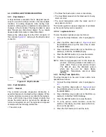
2-4. GENERAL CONTROL OPERATION.
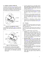
) located on each
side of the control head provides fingertip control for
driving the truck. Rotate the control in the direction you
want to travel. The farther you rotate the control from
the neutral position, the faster the truck will travel.
Figure 2-3. Forward/Reverse Control
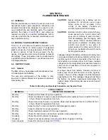
The pushbutton switches (See
), located on
the front of the control head activate the lift, lower, tilt
and horn.
Figure 2-4. Pushbutton Switches
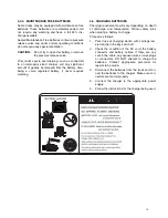
2-5. DRIVING AND STOPPING PROCEDURES.
1.
Connect the batteries and turn on the key switch.
Grasp the grips of the steering head so that the
speed control can be comfortably operated by
either thumb.
2.
Lower the steering arm to a comfortable position
above horizontal to disengage the brake and to
energize the electrical circuits. If the truck is not
moved, the electrical circuits will time out and will
deenergize. See
3.
To move forward (with load in front), slowly press
the speed control forward. See
. Press
the forward speed control farther to increase
speed.
4.
To slow down or stop, release the speed control
and lower or raise the steering arm to the horizon-
tal or vertical position. See
. In those
positions, the brake engages, slowing or stopping
the truck.
5.
Procedures for movement in reverse are the
same as in the forward direction except slowly
press the speed control backward. See
.
2-5.1. Stopping
The brake pattern of the truck depends on the ground
conditions. The driver must take this into account
when operating the truck.
The driver must be looking ahead when traveling. If
there is no hazard, brake moderately to avoid moving
the load.
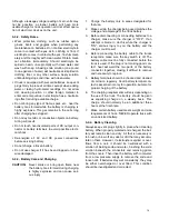
There are four different ways to stop the truck:
1.
Plugging
: This electrical braking function con-
sists of rotating the speed control lever in the
opposite direction of travel and then releasing it
when the truck stops. Plugging is a convenient
way to stop the truck during normal operation. If
the control is not released, the truck will acceler-
ate in the opposite direction.
2.
: The brake is fully
applied by lowering or raising the steering arm.
(See
) All traction control power is shut
off when the brake is engaged. When the steering
arm is in the upright position, the brake acts as a
parking brake. Deadman braking occurs when the
handle is released and spring action raises steer-
ing arm to the upright position.
3.
Emergency braking
: Press the emergency brake
switch, all electrical functions are cut out and the
truck automatically brakes.
4.
Regenerative braking: If the speed control lever is
released, the truck automatically brakes regener-
atively. When the speed is below .5 MPH, the
brake applies
R6617
R6899
10
Summary of Contents for BGL-22
Page 12: ...NOTES 12...
Page 18: ...NOTES 18...
Page 34: ...NOTES 34...
Page 39: ...Figure 5 4 Cap Assembly R6878 39...
Page 42: ...Figure 6 1 Transmission Motor Brake Assembly R6879 42...
Page 44: ...Figure 7 1 Transmission Motor Brake Assembly R6879 44...
Page 45: ...Figure 7 2 Load Wheels R6882 45...
Page 46: ...NOTES 46...
Page 48: ...Figure 8 2 Elevation System Telescopic R6883 48...
Page 50: ...Figure 8 3 Mast TRIMAST R6884 50...
Page 52: ...NOTES 52...
Page 54: ...Figure 9 1 Hydraulic System R6886 54...
Page 56: ...Figure 9 3 Hydraulic System TRIMAST R6888 56...
Page 58: ...Figure 9 4 Elevation System Telescopic R6883 58...
Page 59: ...Figure 9 5 Lift Cylinder Telescopic R6889 59...
Page 61: ...Figure 9 6 Elevation System TRIMAST R6884 61...
Page 62: ...Figure 9 7 Free Lift Cylinder TRIMAST R6890 62...
Page 64: ...Figure 9 8 Secondary Lift Cylinder TRIMAST R6891 64...
Page 67: ...Figure 9 10 Tilt Cylinder R6893 67...
Page 68: ...NOTES 68...
Page 70: ...Figure 10 1 Electrical System R6478 R6894 70...
Page 71: ...Figure 10 2 Electrical Panel R6478 R6895 71...
Page 73: ...Figure 10 3 Transmission Motor Brake Assembly R6879 73...
Page 74: ...NOTES 74...
Page 75: ...SECTION 11 OPTIONAL EQUIPMENT 75...
Page 76: ...NOTES 76...
Page 78: ...Figure 12 1 Steering System R6876 78...
Page 80: ...Figure 12 2 Control Head R6877 80...
Page 82: ...Figure 12 3 Cap Assembly R6878 82...
Page 85: ...NOTES 85...
Page 86: ...Figure 12 5 Transmission Motor Brake Assembly R6879 86...
Page 89: ...NOTES 89...
Page 90: ...Figure 12 7 Frame R6881 90...
Page 92: ...Figure 12 8 Load Wheels R6882 92...
Page 94: ...Figure 12 9 Elevation System Telescopic R6883 94...
Page 96: ...Figure 12 10 Elevation System TRIMAST R6884 96...
Page 98: ...Figure 12 11 Lift Carriage R6815 98...
Page 101: ...NOTES 101...
Page 102: ...Figure 12 13 Hydraulic System R6665 102...
Page 104: ...Figure 12 14 Pump Motor R6886 104...
Page 107: ...NOTES 107...
Page 108: ...Figure 12 16 Hydraulic System TRIMAST R6888 108...
Page 110: ...Figure 12 17 Tilt Cylinder Mounting R6892 110...
Page 112: ...Figure 12 18 Lift Cylinder Telescopic R6889 112...
Page 114: ...Figure 12 19 Free Lift Cylinder TRIMAST R6890 114...
Page 116: ...Figure 12 20 Secondary Lift Cylinder TRIMAST R6891 116...
Page 118: ...Figure 12 21 Tilt Cylinder R6893 118...
Page 120: ...Figure 12 22 Electrical System R6894 120...
Page 123: ...NOTES 123...
Page 124: ...Figure 12 24 Drive Motor R6630 124...
Page 128: ...NOTES 128...
Page 129: ...129...


