background image

5 - 10 - 15 x 1/1 GN ANALOGIC


22


4.4 STARTING THE OVEN 


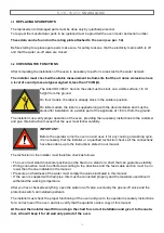
Ensure that water supply are turned on and that the electricity supply is switched on. 
Select the cooking time with the timer (C) that goes up to a maximum of 120 minutes; for longer cooking 
times, select the (∞) nonstop position. 


When the timer is on and the door is closed the cooking cycle starts together with the electric fan, heating 
and steam generation, if selected. 
When the set time is finished a buzzer signals that cooking is finished and all the functions stop. 
When selecting the cooking time always remember the time needed to pre-heat the oven. 
It ‘a good practice to observe this caution before introducing the food to be cooked in the oven. 

4.5  AUXILIARY COMMANDS AND CONTROLS 

4.5A Internal cooking chamber lighting 

All “ANALOG” models are equipped with internal light bulb. Its activation is controlled by the button (D). 


4.5B Cooking chamber preheating 


It is always advisable to pre-heat the oven before cooking food. 
The time needed to heat the oven should be set taking into account that in the hot air convection cycle it 
takes about 10 minutes to reach 220°C. 
Having selected the desired time and temperature, switch the oven on without food inside. 
At the end of the set time the ring signals that cooking can start. 
In the steam cycle it is always advisable to preheat the oven, turning the steam adjuster knob round to 
MAX, for 10 minutes without opening the door. 


4.5C Release valve 

(Fig. 2) 


All models are equipped with this system, which regulate the humidi- 
ty inside the cooking chamber. 


The steam relief valve is opened and closed by rotating knob (A). 


4.5 

D Autoreverse (OPTIONAL) 


Autoreverse function is an optional. 


When it is installed, its activation is controlled by the H switch, placed 
on the lower part of the control panel. 


By pressing H switch, Autoreverse function, that reverses the fan rota- 
tion every 4 minutes to improve cooking uniformity, is activated. 


Activation is confirmed by switch pilot light, which is on. 


4.6 

TURNING THE OVEN OFF 


The oven is turned off by turning the cycle selector knob round to position 0. 

 Fig. 2  

Summary of Contents for 10x1/1 GN

Page 1: ... COMBI DIRECT 105 110 115 ANALOGIC EN 10 2017 CONVECTION STEAM OVEN INSTRUCTIONS FOR THE INSTALLATION USE AND MAINTENANCE Pentland Wholesale Ltd Blizzard House Unit17 Walker Industrial Estate Walker Road Blackburn Lancashire BB1 2QE TEL 01254 614444 Email sales pentlandwholesale co uk ...

Page 2: ...arts replacing 3 2 Checking the functions USE AND MAINTENANCE 4 0 Instructions for a safe use of the oven 4 0A Max food loading 4 1 Programming and operation Mod Convection Humidification 4 1A Components description of control panel Mod Convection Humidification 4 2 Programming and operation Mod Combi Direct 4 2A Components description of control panel Mod Combi Direct 4 4 Starting the oven 4 5 Au...

Page 3: ...ut by d qualified personnel only 1 0 DECLARATION OF CONFORMITY The Manufacturer declares that the appliances conform to the EEC norms They must be installed in accordance with current standards especially regarding aeration of the prem ises and the exhaust gas evacuation system Note The Manufacturer declines all and every responsibility for any direct damages caused by an incorrect use wrong insta...

Page 4: ...136 A Electrical connection B Water inlet Ø 3 4 C Water drainage Ø 40 mm D Cooking chamber relief valve 5 x 1 1 GN 1 2A Dimensions mod 5 x 1 1 GN Dimensions Capacity Trays distance Empty weight mm 709 x 827 x h 598 5 x 1 1 GN 10 x 1 2 GN 67 mm 70 kg O 40 B 73 A C D 60 4 467 1 827 4 48 7 528 6 20 5 1294 5 597 8 ...

Page 5: ...lectrical connection B Water inlet Ø 3 4 C Water drainage Ø 40 mm D Cooking chamber relief valve 10 x 1 1 GN 1 2B Dimensions mod 10 x 1 1 GN Dimensions Capacity Trays distance Empty weight mm 709 x 827 x h 932 10 x 1 1 GN 20 x 1 2 GN 67 mm 90 kg 246 O 40 328 B 63 73 A C D 60 4 467 1 827 4 863 6 932 8 20 5 1294 5 ...

Page 6: ... mm D Cooking chamber relief valve 15 x 1 1 GN 1 2C Dimensions mod 15 x 1 1 GN Dimensions Capacity Trays distance Empty weight mm 749 x 846 x h 1655 15 x 1 1 GN 30 x 1 2 GN 67 mm 160 kg D 31 9 686 2 749 2 31 1 266 O 40 348 B 6373 A C D D 70 161 9 583 2 846 2 101 1 422 7 65 8 507 5 847 423 7 1203 6 27 2 1354 5 1654 5 ...

Page 7: ...5 10 15 x 1 1 GN ANALOGIC 7 5 x 1 1 GN SG 51R 709 2 7 x 1 1GN 646 686 827 563 603 198 500 700 597 8 1297 8 ...

Page 8: ...5 10 15 x 1 1 GN ANALOGIC 8 10 x 1 1 GN SG 51R 709 2 7 x 1 1GN 646 686 827 563 603 198 500 700 932 8 1632 8 ...

Page 9: ...ier and protects the oven from accidental push During moving and installation of the oven the installer must comply with accident prevention regulations in force at the place of installation use of safety shoes gloves etc Remove the packaging taking care not to damage the oven The adhesive film that protects the surfaces made of stainless steel can be removed also after you have positioned the ove...

Page 10: ...er supply single or three phase Serial number of the oven Symbol of European Directive 2012 19 UE Removing the right hand side panel on the oven chassis you find label B On this label the serial number of the oven is repeated In this way the customer or the installer can find the serial num ber of the oven also when the label A is dirty or damaged In the back of the oven near the connector for wat...

Page 11: ...the oven has been installed The same clamp must be easy to access to install equipotential cable after the oven has been installed in compliance with our instructions Install the appliance in a position that allows access to the right side for installation maintenance and technical assistance Maintain the minimum distances between the oven walls rear and right side and either the brick walls or th...

Page 12: ... 5 x 2 5 mm2 10 x 1 1 GN 10 kW 380 415 V 3N 50 Hz 2 x 250 W 9 6 kW 18 0 A 5 x 4 0 mm2 15 x 1 1 GN 15 kW 380 415 V 3N 50 Hz 3 x 250 W 14 4 kW 25 0 A 5 x 6 0 mm2 Model Power loading and voltage no and motor power Heating power Absorbed current Feed cable section 5 x 1 1 GN 6 kW 230 V 50 Hz 1 x 250 W 5 8 kW 27 0 A 3 x 4 0 mm2 10 x 1 1 GN 12 kW 380 415 V 3N 50 Hz 2 x 250 W 11 6 kW 20 0 A 5 x 4 0 mm2 1...

Page 13: ...any risk Before connecting the cable remove the steel protec tion fixed to the ovens base with its specific screws insert the cable in the clamp connector and then in the terminal board zone passing through the hole with the gasket near the terminal board Once the electric connection has been carried out reas semble the steel protection previously removed The specifications of the flexible cable f...

Page 14: ...150 mg litre Chlorine concentration Cl2 less than 0 2 mg litre pH more than 7 Water conductivity included between 50 and 2000 µS cm Attention Water treatment systems that bring to different values to the ones above mentioned automati cally invalidate the guarantee The use of dosing systems designed to prevent the build up of lime scale in pipes i e polyphosphate dosing systems is also prohibited s...

Page 15: ...ntual old joints must not be used again Plumbing connection must be always effected with cold water and rigid pipes Never use hoses to connect the oven to the water main In Convection Humidification models the solenoid valve B supplies the steam generation in Combination cycle Fig 2 5A In Combi Direct models the solenoid valve A supplies the steam generation in Steam cycle the solenoid valve A1 in...

Page 16: ...eel drainpipe The drain must have no trap and be made in rigid pipes that can withstand a temperature of 110 C Under no circumstances must pipe diameter be reduced The actual pipe should be at atmospheric pres sure with the appropriate funnel type air intake If the drainpipe is clogged for any reason steam can escape from the door and bad smells can be created inside in the oven ...

Page 17: ...ondensation of discharge steam optional in convection humidification models it com prises a solenoid valve controlled by a thermostat whose sensor is housed in contact with the discharge The solenoid valve via the injector G lets cold water into the drainpipe to condense the steam when a temperature of 90 C is reached Fig 3 0G Removing the side panel of the oven and acting on the F3 ad juster of t...

Page 18: ...tions to the customer and give this instruction manual that the user must follow carefully IMPORTANT Before the operator turns the oven on and uses it for any cooking or washing cycle it is necessary that the installer or a qualified technician checks all the connections have been done up to the instructions stated in our manual The technician or the installer must therefore check as follows The o...

Page 19: ... check with technical service and replace eventual damaged parts that could alter the proper functioning of the oven or be a danger Often clean the oven following the instructions stated in this manual 4 1 MAX FOOD LOADING Oven model Number of trays Max food loading 105 5 x 1 1 GN 13 kg 110 10 x 1 1 GN 25 kg 115 15 x 1 1 GN 40 kg For a correct comprehension of the terminology used in the following...

Page 20: ...he cooking temperature using thermostat knob B The selector knob A allows a progressive regula tion for humitidy adjustment Cooling down cycle Open the door and turn the cycle selector knob A to the symbol shown on the left This cycle allows the motor fan to work with open door and to cool down quickly the cooking chamber 4 1 PROGRAMMING AND OPERATION MOD CONVECTION HUMIDIFICATION 4 1 A COMPONENTS...

Page 21: ... C Turn the cycle selector knob A to one of the seven adjustment positions among the symbols shown on the left with steam flow from a minimum to a maxi mum and select the cooking temperature using thermostat knob B The selector knob A allows a progressive regula tion for humitidy adjustment Cooling down cycle Open the door and turn the cycle selector knob A to the symbol shown on the left This cyc...

Page 22: ... the oven before cooking food The time needed to heat the oven should be set taking into account that in the hot air convection cycle it takes about 10 minutes to reach 220 C Having selected the desired time and temperature switch the oven on without food inside At the end of the set time the ring signals that cooking can start In the steam cycle it is always advisable to preheat the oven turning ...

Page 23: ...ten the dirty 2 Vaporize the internal part of the cooking chamber with a specific detergent suitable for stainless steel 3 Rinse with a lot of water using a sponge or a hand shower ANY RESIDUES OF DETERGENT COULD DAMAGE THE PARTS IN STAINLESS STEEL WHEN THE COOKING CHAMBER WILL BE HEATED UP The fan must be kept clean to avoid grease and fat from depositing on the blades causing motor revolutions t...

Page 24: ...0 0B Steam cooking with this system at variable tem perature between 50 100 C can be performed cooking very similar to the boiling in water Free steam pressure ensures even and delicate cooking and the loss of vitamins and minerals is almost nothing Cooking times are lower than those in water We always recommend using the perforated G N tray so that when cooking is finished there is no water on th...

Reviews: