blaubergventilatoren.de
CiViC eC dB 1000
7
DESIGN AND OPERATING PRINCIPLE
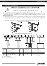
Warm stale extract air from the room flows into the unit, where it is filtered by the extract filter, then air flows through the heat exchanger
and is exhausted outside by the exhaust fan. Cold fresh air from the outside flows into the unit, where it is cleaned by the supply filter.
Then the air flows through the heat exchanger and is directed to the room with the supply fan.
Supply air is heated in the heat exchanger by transferring the heat energy of warm and humid extract air to the cold fresh air. The air
flows are fully separated while flowing through the heat exchanger. Heat recovery minimizes heat losses, which reduces the cost of space
heating in the cold season.
The unit design consists of four blocks rigidly fastened to each other. For maintenance, the unit is equipped with hinged service doors
with locks and service hatches for filter replacement.
Freeze protection is provided in the unit to prevent the heat exchanger from freezing (automatically according to the readings of the
temperature sensors):
• By automatically switching off the supply fan.
• By means of a bypass duct with a bypass damper. The damper automatically opens the bypass air duct, directing the supply air flow
bypassing the heat exchanger.
• By automatically turning the preheater on.
A freezing danger appears if the exhaust air temperature downstream of the heat exchanger is below +5 °C and the intake air temperature
upstream of the heat exchanger is below -3 °C. After increase of the exhaust air temperature the unit reverts to the previous operation
mode.
The difference between the supply and extract air flows temperature leads to condensate generation. Condensate is collected in the
drain pan and is removed outside through the drain pipe.
The control unit inside of the unit enables power supply and connection of the external devices.
Depending on the model, the unit includes a preheater and a reheater (CIVIC EC DBE2 1000) or only a preheater (CIVIC EC DBE 1000) for
warming up of the intake air flow. The preheater prevents freezing of the heat exchanger and is located in the intake air duct upstream
of the heat exchanger. The reheater is located in the supply air duct downstream of the heat exchanger.
The air handling unit has a possibility to connect the following sensors:
• humidity sensor
• CO2 sensor
• VOC sensor
The unit can be used with a vertical duct connection block.
The vertical connection block is not included in the delivery set and must be ordered separately.


