BLAUBERG Ventilatoren Altero 150 T User Manual Download Page 7

POWER OFF THE POWER SUPPLY PRIOR TO ANY OPERATIONS WITH THE UNIT.

THE UNIT MUST BE CONNECTED TO POWER SUPPLY BY A QUALIFIED ELECTRICIAN.

THE RATED ELECTRICAL PARAMETERS OF THE UNIT ARE GIVEN ON THE 

MANUFACTURER’S LABEL.

•  The unit is rated for connection to 1~120 V/60 Hz power mains, depending on the model, according to the wiring diagram. 
•  The unit must be connected to power mains using insulated electric conductors (cables, wires). The actual wire cross section 

selection must be based on the maximum load current, maximum conductor temperature depending on the wire type, insulation, 
length and installation method. 

•  The external power input must be equipped with an automatic circuit breaker built into the stationary wiring to open the electric 

circuit in case of overload or short-circuit. The circuit breaker installation place must provide quick access for emergency shutdown 
of the unit. The trip current of the automatic circuit breaker must exceed the maximum current consumption of the unit (refer to 
the technical data table). The recommended trip current of the circuit breaker is the next current in the standard trip current row 
following the maximum current of the connected unit.  The automatic circuit breaker is not included in the delivery set.

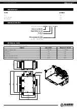
Access to the control unit

To access the control unit, undo the screws securing the 
removable electric mounting plate and pull it towards you until 
it stops. 
Pull the power cable through the glands on the side of the 
control unit and make the electrical connections as shown in 
the wiring diagram. 


L  N  PE  L  N  PE

Wiring diagram example


X1

QF*

PE

N

L

PE

N

L

L

N PE

PE

N

L

PE

N

L

24 V

E   X   H

S   U   P

~24 V

S1*

S2*

~120 V

~120 V

EXH, SUP, 24V

Connectors on the board in the control unit 

X1

Terminal block in the control unit

S1*, S2*

External sensors 

QF*

Circuit breaker 

*Additionally connected devices are purchased separately. 

CONNECTION TO POWER MAINS

www.blaubergventilatoren.de

altero 150 T

7

Summary of Contents for Altero 150 T

Page 1: ...Inline reversible fan EN USER S MANUAL Altero 150 T...

Page 2: ...t in an injury or unit damage After a careful reading of the manual keep it for the entire service life of the unit While transferring the unit control the user s manual must be turned over to the rec...

Page 3: ...he unit When the unit generates unusual sounds odour or emits smoke disconnect it from power supply and contact the Seller Do not open the unit during operation Do not direct the air flow produced by...

Page 4: ...ons timer Mains parameters V Hz _ 230 50 by default 120 60 120 V 50 Hz The unit is rated as a class II electric appliance Options Altero 150T Altero 150T 120 60 Supply voltage V Hz 1 230 50 1 120 60 P...

Page 5: ...amper with an electric actuator Switch Control unit LED Service panel The reversible fan supplies fresh air to the room and extracts humid air from the room Fresh air is delivered to the room with the...

Page 6: ...t mounting should be selected by the service technician Washer Nut Threaded rod Vibration absorbing rubber WARNING To get the best performance of the unit and to minimize turbulence induced air pressu...

Page 7: ...shutdown of the unit The trip current of the automatic circuit breaker must exceed the maximum current consumption of the unit refer to the technical data table The recommended trip current of the ci...

Page 8: ...lowing operations 1 Fan maintenance once a year Some dust may accumulate inside the fans and reduce the fan performance and supply air flow Clean the fans with a cloth or a soft brush Do not use water...

Page 9: ...AND TRANSPORTATION REGULATIONS Store the unit in the manufacturer s original packaging box in a dry closed ventilated premise with temperature range from 5 C to 40 C and relative humidity up to 70 Sto...

Page 10: ...nty repair the user must provide the unit the user s manual with the purchase date stamp and the payment paperwork certifying the purchase The unit model must comply with the one stated in the user s...

Page 11: ...unit is installed pursuant to the requirements stated in the present user s manual Installation Stamp Company name Address Phone Number Installation Technician s Full Name Installation Date Signature...

Page 12: ...www blaubergventilatoren de B184EN 03...

Reviews: