BLAUBERG Ventilatoren 4058448022999 User Manual Download Page 20

www.blaubergventilatoren.de

vento expert (Duo) a50(30)-1 Pro/Pro3

20

MANUFACTURER’S WARRANTY

The product is in compliance with EU norms and standards on low voltage guidelines and electromagnetic compatibility. We hereby 
declare that the product complies with the provisions of Electromagnetic Compatibility (EMC) Directive 2014/30/EU of the European 
Parliament and of the Council, Low Voltage Directive (LVD) 2014/35/EU of the European Parliament and of the Council and CE-marking 
Council Directive 93/68/EEC. This certificate is issued following test carried out on samples of the product referred to above.
The manufacturer hereby warrants normal operation of the unit for 24 months after the retail sale date provided the user's observance 
of the transportation, storage, installation, and operation regulations. Should any malfunctions occur in the course of the unit operation 
through the Manufacturer's fault during the guaranteed period of operation, the user is entitled to get all the faults eliminated by the 
manufacturer by means of warranty repair at the factory free of charge. The warranty repair includes work specific to elimination of faults 
in the unit operation to ensure its intended use by the user within the guaranteed period of operation. The faults are eliminated by means 
of replacement or repair of the unit components or a specific part of such unit component.

The warranty repair does not include: 

•  routine technical maintenance
•  unit installation/dismantling 
•  unit setup
To benefit from warranty repair, the user must provide the unit, the user's manual with the purchase date stamp, and the payment 
paperwork certifying the purchase. The unit model must comply with the one stated in the user’s manual. Contact the Seller for warranty 
service. 

The manufacturer’s warranty does not apply to the following cases:

•  User’s failure to submit the unit with the entire delivery package as stated in the user’s manual including submission with missing 

component parts previously dismounted by the user.

•  Mismatch of the unit model and the brand name with the information stated on the unit packaging and in the user's manual.
•  User’s failure to ensure timely technical maintenance of the unit.
•  External damage to the unit casing (excluding external modifications as required for installation) and internal components caused 

by the user.

•  Redesign or engineering changes to the unit.
•  Replacement and use of any assemblies, parts and components not approved by the manufacturer.
•  Unit misuse.
•  Violation of the unit installation regulations by the user.
•  Violation of the unit control regulations by the user.
•  Unit connection to power mains with a voltage different from the one stated in the user's manual.
•  Unit breakdown due to voltage surges in power mains.
•  Discretionary repair of the unit by the user.
•  Unit repair by any persons without the manufacturer’s authorization.
•  Expiration of the unit warranty period.
•  Violation of the unit transportation regulations by the user.
•  Violation of the unit storage regulations by the user.
•  Wrongful actions against the unit committed by third parties.
•  Unit breakdown due to circumstances of insuperable force (fire, flood, earthquake, war, hostilities of any kind, blockades).
•  Missing seals if provided by the user’s manual.
•  Failure to submit the user’s manual with the unit purchase date stamp.
•  Missing payment paperwork certifying the unit purchase.

FOLLOWING THE REGULATIONS STIPULATED HEREIN WILL ENSURE A LONG AND 

TROUBLE-FREE OPERATION OF THE UNIT.

USER’S WARRANTY CLAIMS SHALL BE SUBJECT TO REVIEW ONLY UPON PRESENTATION 

OF THE UNIT, THE PAYMENT DOCUMENT AND THE USER’S MANUAL WITH THE 

PURCHASE DATE STAMP.

Summary of Contents for 4058448022999

Page 1: ...Single room reversible energy recovery ventilator USER S MANUAL EN Vento Expert A50 1 Pro Vento Expert A50 1 Pro3 Vento Expert Duo A30 1 Pro ...

Page 2: ...e Vento Expert Duo A50 30 1 Pro Pro3 unit and all its modifications Technical and maintenance staff must have theoretical and practical training in the field of ventilation systems and should be able to work in accordance with workplace safety rules as well as construction norms and standards applicable in the territory of the country The information in this user s manual is correct at the time of...

Page 3: ... the entire service life of the unit While transferring the unit control the user s manual must be turned over to the receiving operator UNIT INSTALLATION AND OPERATION SAFETY PRECAUTIONS Disconnect the unit from power mains prior to any installation operations Unpack the unit with care The unit must be grounded While installing the unit follow the safety regulations specific to the use of electri...

Page 4: ...stances in close proximity to the unit When the unit generates unusual sounds odour or emits smoke disconnect it from power supply and contact the Seller Do not open the unit during operation Do not direct the air flow produced by the unit towards open flame or ignition sources Do not block the air duct when the unit is switched on In case of continuous operation of the unit periodically check the...

Page 5: ...rous materials coarse dust soot and oil particles or environments favourable for the formation of hazardous substances toxic substances dust pathogenic germs Name Vento Expert A50 1 Pro Pro3 Vento Expert Duo A30 1 Pro Indoor unit of the ventilator 1 pc 1 pc Air duct 1 pc 1 pc Air flow distributor 3 6 pcs Sound absorbing material 1 pc Assembled cartridge 1 pc 1 pc Outer ventilation hood 1 pc 1 pc R...

Page 6: ...l are indicated on the unit casing The air duct length depends on the unit model refer to the Designation Key section page 6 The supplied ventilation hood model depends on the ventilator model The overall dimensions of the outer ventilation hood the required outside protrusion length of the air duct A and the mounting sequence of the hood are stated in its mounting instruction The overall dimensio...

Page 7: ...tor Frontpartoftheindoorunitwithafrontpanel Fulfils the decorative function The design enables to shut off the air duct in case of an extended downtime of the ventilator The front part of the Vento Expert Duo unit is used for air filtration Back part of the indoor unit The unit includes a circuit control board and basic controls located on the side part Back part of the indoor unit The unit includ...

Page 8: ...e of the ventilator fans operates in the air extract mode and the other one operates in the air supply mode at a set speed The fans do not change their rotation direction Boost if the sensor is actuated the ventilator follows one of two functioning algorithms set via the DIP switch during the ventilator setup For details see page 14 The DIP switch is set to OFF the ventilator runs in the extract m...

Page 9: ...500 min 500 min 500 2 Install the air duct in the wall and fix it with mounting foam The air duct end must protrude for the distance that enables installation of the outer ventilation hood see the User s manual for the outer ventilation hood A min 3 mm Fill the gaps between the wall and the hole with a mounting foam Foam wedge Install the air duct in the wall in such a way so it protrudes from the...

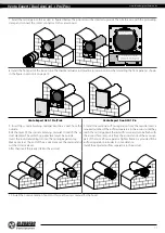
Page 10: ...the master plate 4 Unlatch and detach the front part of the indoor unit from its back part The thermal actuator rod must be in lower position when installing the front panel of the Vento Expert A50 1 Pro unit 5 Fix the back part of the indoor unit on the wall with the screws supplied with the mounting kit of the ventilator Remove the two retaining screws from the left transparent cover to enable a...

Page 11: ...from the outside Roll the layer of the sound absorbing material to match the air duct diameter The protecting paper layer must be outside Insert the sound absorbing roll into the cartridge against stop Make a mark at the end of the air duct remove the material and cut the roll as marked After that insert the ready roll into the air duct 9 Install the sectional air flow separators from the outside ...

Page 12: ... only The actual conductor cross section selection must be based on its type maximum permissible heating insulation length and installation method Use copper wires for all the electric connections Connect the ventilator to power mains in compliance with the wiring diagram EXTERNAL CONNECTIONS DIAGRAM The ventilator design enables connecting external devices with a normally open contact NO contact ...

Page 13: ...Slave 1 Slave N N L N L In Gnd Gnd Out NO1 NO2 12V N L N L In Gnd Gnd Out NO1 NO2 12V N L N L In Gnd Gnd Out NO1 NO2 12V N L Power input АС 100 240V 50 60 Hz to the next ventilator to the next ventilator to the next ventilator VENTILATOR SET UP ON DIP 1 2 3 4 5 6 7 8 Open the rubber plug DIP switch under the plug Prior to operating the ventilator set it up using the DIP switch It is located on the...

Page 14: ...er elapsing of the time set on the turn on delay timer Humidity control is disabled Set value 40 Set value 50 Set value 60 Set value 70 Set value 80 3 4 5 3 4 5 3 4 5 3 4 5 3 4 5 3 4 5 Delay timer During activation of the humidity sensor or any other external device the ventilator switches to higher speed After normalization of the indoor humidity level or any other air parameters the ventilator w...

Page 15: ...or for emergency shutdown of the unit Permanent glowing of the Alarm indicator of the Master unit indicates an alarm in the network of the connected ventilation units Its blinking indicates shutdown of a specific ventilation unit in the network In case of an emergency shutdown of a Vento Expert A50 1 Pro Pro3 unit in the network the defective ventilation unit is marked with the blinking Alarm indi...

Page 16: ...Vento Expert Duo A30 1 Pro Press the side tabs to detach the front part of the indoor unit from its back part and close the air duct Then gently unlatch and remove the front panel from the front part of the indoor unit Remove the air flow separator by pulling one of the side clamps Install the front part of the indoor unit into place Install the front panel on the front part of the indoor unit and...

Page 17: ...l Remove the filters for cleaning Perform all the above operations in the reverse order after cleaning Vento Expert A50 1 Pro Pro3 1 Press the latches on the side of the indoor control unit to take off the front part Please make sure the louver actuator rod is in lower position during re installation of the front panel If the thermal actuator rod is up please wait for about 2 minutes until it goes...

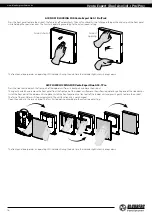
Page 18: ...ery clean the regenerator with a vacuum cleaner at least once a year To reset the filter timer connect the ventilator to the power supply using the circuit breaker before installing the front panel of the indoor unit into its place After that turn the DIP switch No 8 on for not less than 3 seconds and then turn it off For details see page 14 If necessary the remote control battery may be replaced ...

Page 19: ... after transportation at low temperatures allow the unit to warm up at operating temperature for at least 3 4 hours TROUBLESHOOTING POSSIBLE REASONS ANDTROUBLESHOOTING Problem Possible reasons Troubleshooting When switching on the ventilator the fan does not start No power supply Make sure the power supply line is connected correctly otherwise troubleshoot the connection error The motor is jammed ...

Page 20: ...ual Contact the Seller for warranty service The manufacturer s warranty does not apply to the following cases User s failure to submit the unit with the entire delivery package as stated in the user s manual including submission with missing component parts previously dismounted by the user Mismatch of the unit model and the brand name with the information stated on the unit packaging and in the u...

Page 21: ...www blaubergventilatoren de Vento Expert Duo A50 30 1 Pro Pro3 21 ...

Page 22: ...www blaubergventilatoren de Vento Expert Duo A50 30 1 Pro Pro3 22 ...

Page 23: ... INSTALLATION CERTIFICATE The Vento Expert ________________ unit is installed pursuant to the requirements stated in the present user s manual Installation Stamp Company name Address Phone Number Installation Technician s Full Name Installation Date Signature The unit has been installed in accordance with the provisions of all the applicable local and national construction electrical and technical...

Page 24: ...www blaubergventilatoren de B139EN 05 ...

Reviews: