background image

FCC AND IC RFI STATEMENTS

1

FEDERAL COMMUNICATIONS COMMISSION

and INDUSTRY CANADA

RADIO FREQUENCY INTERFERENCE STATEMENTS

Class B Digital Device. 

This equipment has been tested and found to comply with the limits for a Class B

computing device pursuant to Part 15 of the FCC Rules.  These limits are designed to provide reasonable
protection against harmful interference in a residential installation.  However, there is no guarantee that
interference will not occur in a particular installation.  This equipment generates, uses, and can radiate radio
frequency energy, and, if not installed and used in accordance with the instructions, may cause harmful
interference to radio communications.  If this equipment does cause harmful interference to radio or
telephone reception, which can be determined by turning the equipment off and on, the user is encouraged to
try to correct the interference by one of the following measures:

• Reorient or relocate the receiving antenna.

• Increase the separation between the equipment and receiver.

• Connect the equipment into an outlet on a circuit different from that to which the receiver is connected.

• Consult an experienced radio/TV technician for help.

CAUTION

Changes or modifications not expressly approved by the party responsible for
compliance could void the user’s authority to operate the equipment.

To meet FCC requirements, shielded cables and power cords are required to connect this device to a personal
computer or other Class B certified device.

This digital apparatus does not exceed the Class B limits for radio noise emission from digital apparatus set out in the Radio
Interference Regulation of Industry Canada.

Le présent appareil numérique n’émet pas de bruits radioélectriques dépassant les limites applicables aux appareils numériques
de classe B prescrites dans le Règlement sur le brouillage radioélectrique publié par Industrie Canada.

Summary of Contents for ServTray KVT201A

Page 1: ...pport 24 hours a day 7 days a week Call 724 746 5500 or fax 724 746 0746 Mailing address Black Box Corporation 1000 Park Drive Lawrence PA 15055 1018 Web site www blackbox com E mail info blackbox com...

Page 2: ...couraged to try to correct the interference by one of the following measures Reorient or relocate the receiving antenna Increase the separation between the equipment and receiver Connect the equipment...

Page 3: ...por los orificios de ventilaci n 10 El equipo el ctrico deber ser situado fuera del alcance de fuentes de calor como radiadores registros de calor estufas u otros aparatos incluyendo amplificadores q...

Page 4: ...on Centronics is a registered trademark of Centronics Corporation PS 2 is a registered trademark of International Business Machines Corporation UL is a registered trademark of Underwriters Laboratorie...

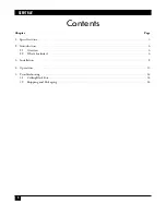
Page 5: ...Y 4 Contents Chapter Page 1 Specifications 5 2 Introduction 6 2 1 Overview 6 2 2 What s Included 6 3 Installation 8 4 Operation 13 5 Troubleshooting 14 5 1 Calling Black Box 14 5 2 Shipping and Packag...

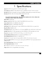
Page 6: ...1A RGB analog H V separate KVT202A Even Odd R G B data sync signal clock Plug n Play VESA VESA DDC 1 2B Viewing Angle KVT201A 60 to 60 H 55 to 45 V typical KVT202A 80 to 80 H 80 to 80 V typical Backli...

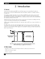
Page 7: ...r Bracket Extension Kit described in Section 2 2 A KVM module is included with the ServTray To control more than one PS 2 server connect the ServTray to a ServSwitch The KVM module comes with a univer...

Page 8: ...epth of a rack cabinet enclosure Depth RMB1 RMB2 RMB3 RMB4 RMB5 inch cm inch cm inch cm inch cm inch cm Minimum 19 5 49 5 22 625 57 5 26 625 67 6 30 5 77 5 34 5 87 6 Maximum 22 375 56 8 27 75 70 5 31...

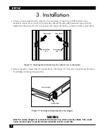
Page 9: ...Figure 3 1 Attaching the rear brackets to the cabinet s rear vertical poles 2 Remove the safety stopper from the console drawer See Figure 3 2 The safety stopper keeps the drawer from sliding out duri...

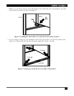
Page 10: ...rawer s two slide rails into the cabinet s brackets 4 Use four 10 32 or 12 24 screws not included to fasten the console drawer onto the front brackets See Figure 3 4 The metal brackets shown in the fi...

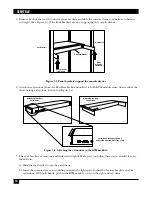
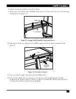
Page 11: ...Attaching the extensions to the KVM module 7 The rear brackets extensions and slide rails fit tightly Make sure you follow these steps carefully for easy installation a Slide the rear brackets onto th...

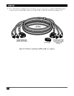
Page 12: ...onnectors on the KVM module and attached cable are firmly mated See Figure 3 8 Figure 3 8 Centronics connectors 11 Connect the power supply to the power jack on the KVM module 12 For operation pull th...

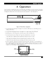
Page 13: ...on a PS 2 CPU via the CPU Cable shown in Figure 3 9 Figure 3 9 Cable for connecting the KVM module to a computer Using the gender changer this cable attaches to the HD15 and 6 pin mini DIN connectors...

Page 14: ...anel on or off via the power switch 3 in Figure 4 1 4 Use the keyboard status keys Num Lock Caps Lock and Scroll Lock to view status The Num Lock key labeled 4 shows the Keyboard Num Lock status on or...

Page 15: ...e a complete description including the nature and duration of the problem when the problem occurs the components involved in the problem any particular application that when used appears to create the...

Page 16: ...1000 Park Drive Lawrence PA 15055 1018 724 746 5500 Fax 724 746 0746 Copyright 2004 Black Box Corporation All rights reserved...

Reviews: