background image















9













®

Installation

Locations

Please consider the following important points when planning the location of 
the ServSwitch Secure USB unit:

•  Situate the unit close to the host computers to which it will be connected 

and also the user console peripherals. 

•  The unit requires a power supply input, so a nearby spare mains power 

outlet will be required. 

•  As keyboard and mouse switching codes are not possible for security reasons, 

the only way to change channels is via the front panel buttons. Therefore, 
the unit should be easily accessible from the user’s normal position.     

•  Please consult the precautions listed within the 

Safety information

 section.

Cabling recommendations

It is vitally important to use good quality shielded cables to minimize the 
risk of signal emissions that may be intercepted. Please follow the following 
recommendations when specifying cables: 

•  DVI cables - should be braid and foil shielded.  
•  VGA cables - should be braid and foil shielded. If DVI-I to VGA style adapters 

are used these should be of the fully ‘canned’ variety. 

•  USB cables - should be braid and foil shielded.  
•  Audio cables - should be braid shielded with fully shielded connectors (not 

unshielded connectors with drain wires). 

We strongly recommend that you fit ferrite cores at both ends of every cable to 
further assist with emission suppression. 

Tamper-evident seals

The primary casing access screws are pre-fitted with tamper-evident seals. It 
may be a policy of your organization to fit proprietary tamper-evident labels 
across certain chassis screws. Additionally, seals could be added between each 
connection and the unit to highlight any connections that have been altered.

IMPORTANT: Do not use the unit if the tamper-evident seals are 

damaged. Do not use if there are any signs of damage to the unit or its 
power supply.

SECT 3

Links overview

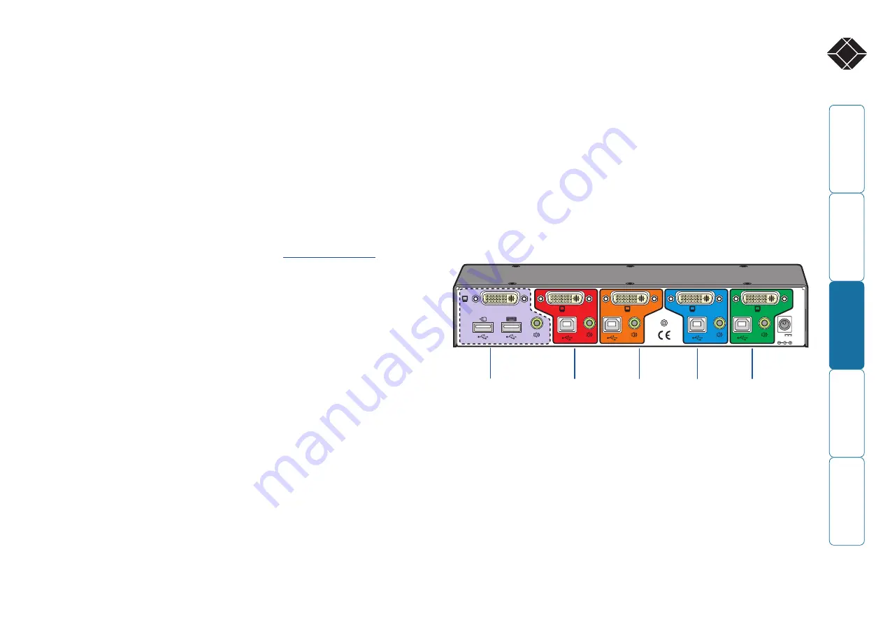
The rear panel of the unit is well marked, however, the diagram below offers 
additional clarity on how best to arrange your connections.
You may have noticed that the indicators on the front panel use different 
colors to represent the various channels. This is done to provide quick and 
effective visual feedback to the operator. Channel 1 has a green indicator 
and is traditionally used for the lowest security connection. The final channel, 
numbered 2 on the two port version and 4 of the four port version, uses a red 
indicator and is usually connected to the highest security connection. These are 
configuration conventions only and are offered as a suggestion - there are no 
technical differences in the operational specifications of the four channels.  

4

3

5V
2.0A

USER CONSOLE

IN

D

O

O

R

U

S

E

O

N

L

Y

1

2

Channel 1  

(green indicator)

Usually used 
for connection 
to the lowest 
security computer/
network.

Channel 4  

(red indicator)

Usually used 
for connection 
to the highest 
security computer/
network.

Console 
connections

Connect directly 
to the operator’s 
keyboard, mouse, 
video display and 
speakers.

Channel 3  

(amber 


indicator)

Channel 2  

(blue 


indicator 
or red 
indicator on 
two channel 

models) 

Summary of Contents for ServSwitch Secure USB

Page 1: ...works you need ServSwitch Secure USB ServSwitch Secure USB SW2008A USB EAL SW4008A USB EAL Order toll free in the U S Call 877 877 BBOX outside U S call 724 746 5500 FREE technical support 24 hours a day 7 days a week Call 724 746 5500 or fax 724 746 0746 Mailing address Black Box Corporation 1000 Park Drive Lawrence PA 15055 1018 Web site www blackbox com E mail info blackbox com Customer Support...

Page 2: ...h Secure USB 7 Keyboard devices 7 Mouse devices 7 Standard items 8 Additional items 8 Installation Locations 9 Cabling recommendations 9 Tamper evident seals 9 Links overview 9 Mounting 10 Making connections 11 Connections to computer systems 11 Connections to user console peripherals 13 Video display EDID information 15 Connection to power supply 16 Operation Selecting computers 17 Error indicato...

Page 3: ...erational procedures must e g re staff vetting and training ensure that as far as is reasonably possible the product is received installed and managed in accordance with the manufacturer s directions This should also ensure that users are not malicious or hostile The product should be installed in an environment that is physically secure Additionally the security office in the organisation purchas...

Page 4: ...o frequency energy and if not installed and used properly that is in strict accordance with the manufacturer s instructions may cause inter ference to radio communication It has been tested and found to comply with the limits for a Class A computing device in accordance with the specifications in Subpart B of Part 15 of FCC rules which are designed to provide reasonable protection against such int...

Page 5: ...r los orificios de ventilación 10 El equipo eléctrico deber ser situado fuera del alcance de fuentes de calor como radiadores registros de calor estufas u otros aparatos incluyendo amplificadores que producen calor 11 El aparato eléctrico deberá ser connectado a una fuente de poder sólo del tipo descrito en el instructivo de operación o como se indique en el aparato 12 Precaución debe ser tomada d...

Page 6: ...sing contains extensive shielding to considerably reduce electromagnetic emissions Additionally the casing has been designed with as few apertures as possible to reduce the possibility of external probing and several primary chassis screws are concealed by tamper evident seals to indicate any unauthorized internal access Shielding extends also to the internal circuitry with all channels providing ...

Page 7: ...el buttons Each selected channel is represented by an individually colored indicator to provide additional visual feedback Clear error indication Any unexpected operation such as an attempt to select two channels simultaneously will be signalled by the ERR indicator accompanied by complete isolation of all channels Secure and shielded casing The casing is shielded to reduce electromagnetic emissio...

Page 8: ...at every switchover to clear stored states 5V 2 0A INDOOR USE ONLY USE R CONSO LE 4 2 3 1 USER CONSOLE 5V 2 0A INDOOR USE ONLY USE R CONSO LE 4 2 3 1 USER CONSOLE Keyboard devices The keyboard used with the switch must be approved against the security policy of your organization and must be plugged directly into the switch s USB keyboard port with no adapters or converters During the life of the p...

Page 9: ... S E C U R E D E S K T O P K V M S W I T C H 5V 2A Power supply plus country specific mains cable Standard items Additional items ServSwitch Secure USB unit SW2008A USB EAL 2 port SW4008A USB EAL 4 port Installation CD ROM Rack brackets Including four screws ...

Page 10: ...amper evident seals It may be a policy of your organization to fit proprietary tamper evident labels across certain chassis screws Additionally seals could be added between each connection and the unit to highlight any connections that have been altered IMPORTANT Do not use the unit if the tamper evident seals are damaged Do not use if there are any signs of damage to the unit or its power supply ...

Page 11: ... 10 Mounting The ServSwitch Secure USB unit offers two main mounting methods Supplied four self adhesive rubber feet Optional rack brackets 5V 2 0A INDOOR USE ONLY 1 USER CONSOLE 4 ...

Page 12: ...uter systems To connect a keyboard and mouse link 1 Wherever possible ensure that power is disconnected from the unit and the host computer s to be connected To connect an audio link 1 Wherever possible ensure that power is disconnected from the unit and the host computer s to be connected 2 At the rear panel of the unit choose the appropriate channel group 1 to 4 and connect an audio link cable t...

Page 13: ... display could cause issues in certain high security installations please see the Video display EDID information section for further details To connect a video input 1 Wherever possible ensure that power is disconnected from the unit and the host computer s to be connected 2 As appropriate connect either a digital or analog video link cable to the required DVI I socket on the rear panel Digital Co...

Page 14: ...aces 1 Wherever possible ensure that power is disconnected from the unit and the host computer s to be connected 2 At the far left side of the rear panel connect the cables from the keyboard and mouse to the USB sockets marked and respectively USER CONSOLE USER CONSOLE To connect speakers 1 Wherever possible ensure that power is disconnected from the unit and the host computer s to be connected 2 ...

Page 15: ...play could cause issues in certain high security installations please see the Video display EDID information section for further details To connect a video display 1 Wherever possible ensure that power is disconnected from the unit and the host computer s to be connected 2 As appropriate connect either a digital or analog video display to the DVI I socket on the far left side of the rear panel Dig...

Page 16: ...set of default data to the EDID memories and no data will be made available to the computers This provides a means of clearing information about previously attached monitors Note Most analog video cards will output a video signal without EDID information In such installations it may be acceptable to disconnect the DDC connections from the ServSwitch Secure USB so that no EDID information is made a...

Page 17: ...do not use an unearthed power socket or extension cable To connect the power supply 1 Attach the output connector of the power supply country specific power supplies are available to the socket on the far right of the rear panel 5V 2 0A INDOOR USE ONLY 2 1 2 When all other connections have been made connect the main body of the power supply to a nearby earthed mains socket ...

Page 18: ...ect the labeled channel When the chosen channel has been connected the adjacent indicator will illuminate continuously to confirm If the indicator flashes then the selected computer is either switched off or disconnected Each channel uses a differently colored indicator to provide additional visual feedback about the chosen channel Channel 1 has a green indicator and is generally configured to lin...

Page 19: ...nces but these will require specialist assistance from Black Box technical support Summary of threats and solutions This section provides a list of potential security threats that the ServSwitch Secure USB might face during operation and the special steps that have been taken to counteract them Threat Solution Microprocessor malfunction or unanticipated software bugs causing data to flow between p...

Page 20: ...ormation about data flowing to another computer The user selects the wrong port Only one simple method of selecting computers is provided The selected port is clearly and unambiguously indicated on the front panel by means of colored lights adjacent to each key switch For high levels of security the screens of high and low security computers should be arranged to look visibly different in general ...

Page 21: ...ot attempt to service the unit yourself Not suitable for use in hazardous or explosive environments or next to highly flammable materials Do not use the power adapter if the power adapter case becomes damaged cracked or broken or if you suspect that it is not operating properly If you use a power extension cable make sure the total ampere rating of the devices plugged into the extension cable do n...

Page 22: ... Consult the supplier or an experienced radio TV technician for help FCC Compliance Statement United States This equipment generates uses and can radiate radio frequency energy and if not installed and used properly that is in strict accordance with the manufacturer s instructions may cause interference to radio communication It has been tested and found to comply with the limits for a class A com...

Page 23: ...tion products to media converters and Ethernet switches all supported by free live 24 7 Tech support available in 30 seconds or less Copyright 2010 Black Box Corporation All rights reserved SW2008A USB EAL SW4008A USB EAL rev 1 2 Black Box Tech Support FREE Live 24 7 Great tech support is just 30 seconds away at 724 746 5500 or blackbox com NETWORK SERVICES Tech support the way it should be ...

Reviews: