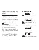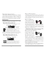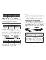
LEDs on MediaConverter Chassis
1-Slot, 4-Slot and 8-Slot chassis include LEDs on the back of the chassis.
P
OWER
Glows green when chassis has power.
A
CTIVITY
This LED blinks green when data is being passed on either
port of a module that does not include Link/Activity LEDs.
NOTE: This LED is not applicable for modules that include Link/Activity LEDs.
LEDs on Power Supplies
P
OWER
Glows green when powered-on.
Installation Troubleshooting
•
During installation, first test the fiber and twisted pair connections with all
troubleshooting features disabled, then enable these features, if desired,
just before final installation. This will reduce the features’ interference with
testing.
•
When working with units where the features cannot be disabled, you must
establish BOTH your twisted pair and fiber connections before the link
LEDs will light!
•
To test a media converter by itself, first make sure you have an appropriate
fiber patch cable, then follow these steps to test:
SStteepp 11::
Connect the media converter to the twisted pair
device with a twisted pair cable.
SStteepp 22::
Loop a single strand of fiber from the transmit port to
the receive port of your media converter.
SStteepp 33::
Verify that you have both twisted pair and fiber link
(see LEDs, below) on your media converter.
NOTE: Use caution when conducting a loopback test; it is possible to
create a network loop if connecting the twsited pair port to an active net-
work switch. Black Box recommends connecting the twisted pair cable
to a PC for this type of test.
•
Make sure to use the appropriate twisted pair cable, and have the
crossover/pass-through switch set correctly if your media converter does
not include
AutoCross.
• If using a high powered device (which is designed for long distance
installations) for a short distance installation, the fiber transmitters
may overdrive the receivers and cause data loss. If this is the case,
you may need to add an optical attenuator to your connection.
For fiber specifications, please contact Black Box for more information.
12
5
Thin Ethernet segments must be proper-
ly terminated at both ends and grounded
at one end. If the BNC port is not ter-
minated correctly, the ACTIVITY light on
the front panel will not glow.
T
W I S T E D
P
A I R
C
R O S S O V E R
/ P
A S S
- T
H R O U G H
C
O N N E C T I O N S
Whether you are using crossover or straight-through CAT5 twisted pair
cabling,
10Mbps and 10/100 Switching Modules
will support both types of
connections by one of the following methods:
AutoCross:
100Mbps (-00) Modules
and
10/100 Switching Modules
include
AutoCross
, a feature that automatically selects between a crossover
workstation or pass-through connection depending on the connected
device.
MDI-II/MDI-X Switch:
All
10Mbps Modules
feature a 2-position switch,
located at position
S1
(see page 3 for location on boards), for selecting a
crossover workstation connection or pass-through connection.
The switch is labeled with “
X”
for a crossover connection (factory default)
and an “
ll
” for a pass-through connection. Select the appropriate setting by
moving the switch to the proper position before installing the media con-
version module. If uncertain whether crossover or pass-through is needed,
set the switch to the position that makes the link LED glow.
Device-Dependent:
The type of twisted pair connection for
100Mbps
Modules
(-20 and -50) modules is determined by the end device to which
the module is connected; these
100Mbps Modules
do not include
AutoCross
or a MDI-II/MDI-X switch.
NOTE:
The appropriate type of cable must be used for a link to be established. Refer to
the documentation for the connected device for information.
T
W I S T E D
P
A I R
C
A B L E
D
I S T A N C E
The twisted pair port on
10Mbps Modules
features a 2-position jumper,
located at position
JP2
, for selecting longer twisted pair cable distances (dis-
tances greater than 100 meters). Place the jumper over both pins for dis-
tances up to 100 meters (factory default). Remove the jumper shunt or
place it on only one pin for distances of 100 meters or more.
NOTE
: The product on the other side of the conversion must be able to support longer cable
distances as well.
T
W I S T E D
P
A I R
C
A B L E
T
Y P E
The twisted pair port on
10Mbps Modules
(-20 and -40) features a
2-position jumper, located at position
JP3
, for selecting either a shielded or
N O T E
When the BNC port is not being used,
Black Box recommends connecting a
50
Ω
terminator to the port at each
end.of the run.

