background image

24/7 TECHNICAL SUPPORT AT 1.877.877.2269 OR VISIT BLACKBOX.COM

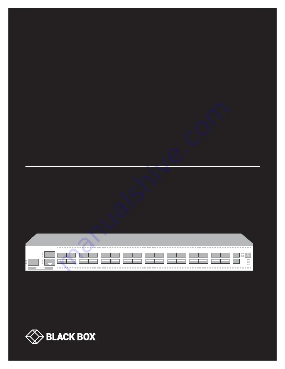
32-PORT 100G 

IP NETWORK 

SWITCH

HARDWARE INSTALLATION GUIDE

EMS100G-32

• • • •


• • • • 

• • • •


• • • • 

• • • • 

• • • • 

• • • • 

• • • • 

• • • • 

• • • • 

• • • •


• • • • 

• • • • 

• • • • 

• • • • 

• • • • 

• • • • 

• • • • 

• • • • 

• • • • 

• • • • 

• • • • 

• • • • 

• • • • 

• • • • 

• • • • 

• • • • 

• • • • 

• • • • 

• • • • 

• • • • 

• • • • 

Summary of Contents for EMS100G-32

Page 1: ...24 7 TECHNICAL SUPPORT AT 1 877 877 2269 OR VISIT BLACKBOX COM 32 PORT 100G IP NETWORK SWITCH HARDWARE INSTALLATION GUIDE EMS100G 32...

Page 2: ...3 3 Rackmounting 12 3 4 Switch Ground 12 3 5 Fans and Airflow 13 3 6 Power 13 3 7 Storing Components 13 4 NEBS COMPLIANCE 14 4 1 Important Information 14 4 2 NEBS Compliant Ground Installation 14 5 I...

Page 3: ...ample of ONiE 35 8 4 3 ONiE Service Discovery 35 9 TROUBLESHOOTING 37 9 1 Contacting Technical Support 37 9 2 Shipping and Packaging 37 APPENDIX A REGULATORY INFORMATION 38 A 1 USA Federal Communicati...

Page 4: ...handling this equipment WARNING Only trained and qualified personnel can install this equipment Read this guide before you install and power up this equipment This equipment contains two power cords...

Page 5: ...tching Capacity 6 4 Tbps Forwarding capacity Up to 4400 Mpps Full Duplex Packet buffer memory 16MB CPU memory 8GB MAC addresses 136 K ARP entries 128K IPv4 Unicast routes 136 K IPv6 Unicast routes 68K...

Page 6: ...dditional file storage One 10 100 1000BaseT Ethernet management port Rangeley central processing unit CPU system with 8GB DDR III RAM Temperature monitoring Software readable thermal monitor Real time...

Page 7: ...2 1 RJ 45 port Links to serial console 3 32 10 25 40 50 100 ports SFP modules install here 4 2 1000M 10G SFP ports SFP modules install here 5 Stack ID Unique number between 1 6 used when stacking swi...

Page 8: ...2 OVERVIEW 2 5 2 BACK PANEL Figure 2 2 shows the back panel of the switch Table 2 3 describes its components FIGURE 2 2 BACK PANEL OF THE SWITCH TABLE 2 3 BACK PANEL COMPONENTS NUMBER IN FIGURE 2 2 C...

Page 9: ...TABLE 2 4 LEDS ON THE SWITCH NUMBER IN FIGURE 2 3 NAME OF LED DESCRIPTION 1 Master LED Off Switch is in Stacking Slave mode Solid green System is in Stacking Master or Standalone mode 2 System LED Off...

Page 10: ...n Normal operation Solid amber Post in process Blinking amber Non critical system error PSU fan failure or power supply failure TABLE 2 5 QSFP28 PORT LEDS NUMBER IN FIGURE 2 3 NAME OF LED DESCRIPTION...

Page 11: ...LED Off No Link Solid green Port link is 2x50 GbE 4 Activity LED Off No link Flashing amber approx 30 ms port link is 2x50 GbE TABLE 2 8 SFP PORT LEDS NUMBER IN FIGURE 2 3 NAME OF LED DESCRIPTION 4 Li...

Page 12: ...to 95 F 10 to 35 F Operating humidity is from 5 to 85 percent noncondensing Storage humidity is from 5 to 95 percent noncondensing In a dry clean well ventilated and temperature controlled room away f...

Page 13: ...low the requirements of the National Electrical Code ANSI NFPA 70 where applicable The switch is powered up as soon as the power cord is connected between the switch and the power source CAUTION Alway...

Page 14: ...ed access area where only trained personnel are allowed access Install and connect your switch to the common bonding network CBN You can also install and connect your switch to the central office Conn...

Page 15: ...ws from the lower left side of your chassis NOTE Keep these screws 2 Remove the bracket assembly from the shipping bag 3 Clean the bracket and lug surfaces thoroughly and apply an anti oxidant solutio...

Page 16: ...US LIVE 24 7 TECHNICAL SUPPORT 1 877 877 2269 CHAPTER 4 NEBS COMPLIANCE FIGURE 4 3 GND LUG ASSEMBLY ATTACHED 5 Install your chassis into your rack using the installation instructions in Chapter 5 6 At...

Page 17: ...nsed reference Read the safety instructions in your Safety Environmental and Regulatory information booklet before you begin NOTE The illustrations in this document are not intended to represent a spe...

Page 18: ...two post center mount or four post threaded 1 With the rail flange ears facing outward place one rail between the left and right vertical posts Align and seat the rear flange rail pegs in the rear ver...

Page 19: ...se a Torx screwdriver to remove the two screws from each front flange ear on the switch side of the rail and remove each casting Retain the castings for future rack requirements It is not necessary to...

Page 20: ...quake Z4 compliant if you use this installation method 1 Slide the plunger bracket rearward until it clicks into place and secure the bracket to the front post flange with two user supplied screws ite...

Page 21: ...s latch castings described in Step 1 1 For this configuration remove the flange ear castings from each end of the rail assemblies To remove the two screws from each flange ear and remove each casting...

Page 22: ...r as the four post configurations 1U FRONT RACK INSTALLATION Configure the rails that are attached to the switch 1 Attach the inner chassis members switch rails to the EMS100G 32 switch Item 3 shows t...

Page 23: ...xidant compound before crimping Also bring any unplated mating surfaces to a shiny finish and coat with an anti oxidant before mating Plated mating surfaces must be clean and free from contamination N...

Page 24: ...When working with optical fibers follow all warning labels and always wear eye protection Never look directly into the end of a terminated or unterminated fiber or connector as it may cause eye damage...

Page 25: ...n the front panel ports and the port pipes is shown FIGURE 5 7 PORT PIPES 5 8 POWERING UP THE SWITCH Supply power to the switch after it is mounted in a rack or cabinet Black Box recommends reinspecti...

Page 26: ...ponents are mishandled Always wear an ESD preventive wrist or heel ground strap when handling the EMS100G 32 and its components 6 1 COMPONENTS The following power supply is available for the EMS100G 3...

Page 27: ...2 Remove the PSU from the electro static bag 3 Insert the PSU into the switch PSU slot Insert the PSU exposed PCB edge connector first The PSU slot is keyed so that the PSU can only be fully inserted...

Page 28: ...he PSU or the switch chassis NOTE If a PSU fails you must replace the entire unit There are no field serviceable components in the PSU To request a hardware replacement contact Black Box Technical Sup...

Page 29: ...me required between fan replacements Check the environmental factors regularly An increase in temperature and or particulate matter in the air might affect performance for example new equipment instal...

Page 30: ...the cooling fans An increase in overall fan speed may indicate a clogged filter You must replace the fan air filters with new filters you cannot clean and reuse the old fan air filters Replacement fil...

Page 31: ...THE TECH TO US LIVE 24 7 TECHNICAL SUPPORT 1 877 877 2269 CHAPTER 7 FANS 7 5 AFTER INSTALLING THE SWITCH After you have securely installed and powered on the switch to configure your switch see your...

Page 32: ...9 male to male adapter 1 Install the provided RJ 45 connector side of the provided cable into the switch console port 2 Install the DB9 female side of the provided copper cable into your PC s serial p...

Page 33: ...switch 5 Install the necessary USB device drivers To download the drivers contact Black Box Technical Support at 877 877 2269 or info blackbox com 6 Open your terminal software emulation program to ac...

Page 34: ...iled No such device or address 4 Add a device to the file systems table fstab and mount the file systems recommended ONIE vi etc fstab FSTAB entry for the ONIE BOOT partition mounted on boot LABEL ONI...

Page 35: ...loading and updating ONIE from a URL ONIE Embed ONIE For downloading and updating ONIE from a URL and erases any installed O ONIE Diag ONIE Run Diagnostic package for EMS100G 32 Run Black Box Networki...

Page 36: ...255 255 0 To display the IP address use the ifconfig eth0 command as shown ONIE ifconfig eth0 eth0 Link encap Ethernet HWaddr 90 B1 1C F4 9C 76 inet addr 10 11 53 33 Bcast 10 255 255 255 Mask 255 0 0...

Page 37: ...e will be able to provide more efficient and accurate assistance if you have a complete description including the nature and duration of the problem when the problem occurs the components involved in...

Page 38: ...ation of this equipment in a residential area is likely to cause harmful interference in which case users will be required to take whatever measures necessary to correct the interference at their own...

Page 39: ...tes que impidan el flujo de aire por los orificios de ventilaci n 10 El equipo el ctrico deber ser situado fuera del alcance de fuentes de calor como radiadores registros de calor estufas u otros apar...

Page 40: ...the limits for Class A Information Technology Equipment according to CISPR 22 European Standard EN 55022 The limits for Class A equipment were derived for commercial and industrial environments to pr...

Page 41: ...1st Edition EN 60825 1 Safety of Laser Products Part 1 Equipment Classification Requirements and User s Guide EN 60825 2 Safety of Laser Products Part 2 Safety of Optical Fibre Communication Systems...

Page 42: ...system according to applicable local and national regulations Black Box encourages owners of information technology IT equipment to responsibly recycle their equipment when it is no longer needed Wast...

Page 43: ...e consequential or cost of cover damages resulting from any errors in the product information or specifications set forth in this document and Black Box Corporation may revise this document at any tim...

Page 44: ...NEED HELP LEAVE THE TECH TO US LIVE 24 7 TECHNICAL SUPPORT 1 877 877 2269 COPYRIGHT 2018 BLACK BOX CORPORATION ALL RIGHTS RESERVED EMS100G 32_INSTALL_REV1 PDF...

Reviews: