background image

Order toll-free in the U.S.: Call 877-877-BBOX (outside U.S.  
call 724-746-5500)  •  FREE technical support 24 hours a day, 7 days  
a week: Call 724-746-5500 or fax 724-746-0746  •  Mailing address:  
Black Box Corporation, 1000 Park Drive, Lawrence, PA 15055-1018
Web site: www.blackbox.com   •   E-mail: [email protected]

Customer 

Support 

Information

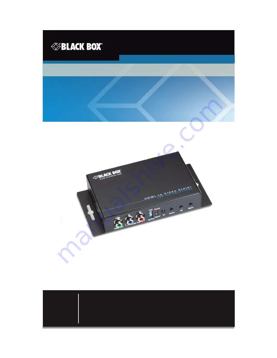
Converts digital HDMI and audio to component/
CVBS  video with either digital audio (S/PDIF) or 
analog stereo audio.

HDMI to Video Scaler and Converter

          AVSC-HDMI-VIDEO

Summary of Contents for AVSC-HDMI-VIDEO

Page 1: ...00 or fax 724 746 0746 Mailing address Black Box Corporation 1000 Park Drive Lawrence PA 15055 1018 Web site www blackbox com E mail info blackbox com Customer Support Information Converts digital HDM...

Page 2: ...ther trademarks mentioned in this manual are acknowledged to be the property of the trademark owners Disclaimer Black Box Network Services shall not be liable for damages of any kind including but not...

Page 3: ...s may be necessary to correct the interference Changes or modifications not expressly approved by the party responsible for compliance could void the user s authority to operate the equipment This dig...

Page 4: ...netes que impidan el flujo de aire por los orificios de ventilaci n 10 El equipo el ctrico deber ser situado fuera del alcance de fuentes de calor como radiadores registros de calor estufas u otros ap...

Page 5: ...aparato ha sido tirado o su cubierta ha sido da ada Safety Notice Please read and follow the safety instructions to protect yourself from possible injury and to minimize the risk of damage to the uni...

Page 6: ...f Contents 1 Specifications 7 2 Overview 9 2 1 Introduction 9 2 2 Features 9 2 3 What s Included 9 2 4 Hardware Description 10 3 Connection Diagram 12 4 OSD Menu 13 5 Operation 15 6 Troubleshooting 22...

Page 7: ...contact discharge Core chipset 2 kV Firmware Update via USB Port Frequency Bandwidth Output video 165 MHz Input video 74 25 MHz IR Sensor Receives IR commands from the IR remote User Controls 1 DIP s...

Page 8: ...ns continued Environment Temperature Tolerance Operating 32 to 104 F 0 to 40 C Storage 4 to 140 F 20 to 60 C Relative Humidity 20 90 noncondensing Power Power supply 5 VDC 2 A Consumption 5 Watts max...

Page 9: ...nnect to your PC LCD and PC speakers The device also enables users to connect full digital video and audio to a CVBS monitor and S PDIF equipped audio receiver and amplifier for maximum compatibility...

Page 10: ...10 Chapter 2 Overview 2 4 Hardware Description Figures 2 1 and 2 2 show the front and back panels of the scaler Table 2 1 describes its components 1 2 3 4 5 6 7 7 7 Figure 2 1 Front panel 8 9 10 11 1...

Page 11: ...tor 1 Red LED for Power 1 Green LED for Video Signal 6 IR sensor Used to receive the IR commands from IR remote 7 Push button Down button 7 Push button Up button 7 Push button Menu Enter button 5 2 LE...

Page 12: ...12 Chapter 3 Connection Diagram 3 Connection Diagram RCA L cable Rear AVSC HDMI VIDEO front top and back bottom DVD player Flat panel display Digital audio in HDMI cable Front YPbPr RCA R cable Rear...

Page 13: ...lt Pattern Disable Default White Cross Hatch Color Gray Windows H Ramp W HRamp W VRamp Diagonal EDID Audio CH 2ch 7 1ch 2 Image Contrast 0 255 Default 0 Brightness 0 255 Default 0 Saturation 0 255 Def...

Page 14: ...menu Option Description Settings 3 Adjustment Under Over Scan 50 50 Default Off Aspect Ratio 16 9 Default 4 3 H Mirror Off Default On V Mirror Off Default On H Shift 100 100 Default 0 V Shift 50 50 De...

Page 15: ...00 blackbox com Page 15 Chapter 5 Operation 5 Operation Method A Push in Button See Figure 5 1 Down Up Menu Figure 5 1 Location of push buttons on the scaler Method B IR Remote Control Figure 5 2 Remo...

Page 16: ...IO Aspect ratio change BLANK Blank video EXIT Exit OSD ENTER Enter key UP Up key LEFT Left key RIGHT Right key DOWN Down key MENU Menu on INPUT INFO Source resolution information 1080p60 Select 1080p6...

Page 17: ...2 IR remote control through mini USB port screen functions Number in Figure 5 3 Function 1 COM Port Selection 2 COM Port Detection Button 3 Output Setup Button 4 Image Button 5 Adjustment Button 6 Sy...

Page 18: ...e 18 Chapter 5 Operation 1 COM Port Selection Please select the COM PORT application Figure 5 4 Select COM port 2 COM Port Detection Button Click on the curved arrow button to detect the COM PORT 3 Ou...

Page 19: ...724 746 5500 blackbox com Page 19 Chapter 5 Operation 4 Image Button Figure 5 6 5 Adjustment Button Figure 5 7...

Page 20: ...lackbox com Page 20 Chapter 5 Operation 6 System Button Figure 5 8 System screen 1 In Sync Info To view the current input resolution 2 Factory Reset Button 3 Firmware Update Button Figure 5 9 Firmware...

Page 21: ...STEP E Click on the Load File button to select the firmware file STEP F Click on the Burn button to start the firmware update process STEP G Unplug the Mini USB connector from the device STEP H Set th...

Page 22: ...ore efficient and accurate assistance if you have a complete descrip tion including the nature and duration of the problem when the problem occurs the components involved in the problem any particular...

Page 23: ...724 746 5500 blackbox com Page 23 NOTES...

Page 24: ...wer and surge protection products to media converters and Ethernet switches all supported by free live 24 7 Tech support available in 60 seconds or less Copyright 2014 Black Box Corporation All rights...

Reviews: