


◈
Information
This Installation Guide includes a brief outline of information necessary for product
installation. For more detailed installation information, please refer to the user manual in the
enclosed CD. The contents of the CD include the following.
1. Manual: User Manual, Code Chart, Control Commands
2. Drivers: Windows Drivers, OPOS Drivers
3. Utilities: a Logo download tool and a virtual memory switch control tool
We at BIXOLON maintain ongoing efforts to enhance and upgrade the functions and quality
of all our products. In following, product specifications and/or user manual content may be
changed without prior notice.
◈
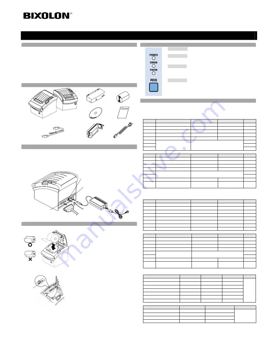
Components
Cable cover
Paper Roll
SRP-350plusIIC SRP-350plusIIA
Procuct Installation CD
Procuct Installation CD
Procuct Installation CD
CD
Installation Guide
USB A-A JACK
AC/DC Adaptor
Power cord
◈
Connecting the cables
1. Turn off the printer and the host ECR (host computer).
2. Plug the power cord into the Adaptor, and then plug the Adaptor into the power connector
of the printer.
3. Check the interface cable (Serial, Parallel, USB, or Ethernet), and connect the interface
connector cable accordingly.
4. Plug the drawer kick-out cable into the drawer kick-out connector on the printer.
◈
Installing the Paper Roll
1. Open the paper roll cover by pressing the cover-
open button.
2. Insert a new paper roll, making sure to align it
properly.
3. Pull out a small amount of paper, and close the
cover.
※
Note
When closing the cover, press down on the center
of the cover to ensure that the paper is in contact
with the roller.
※
Note: Adjusting the Paper Near-End Sensor
The SRP-350plusIIC has a paper near-end sensor
that provides notice that the paper roll is nearly
exhausted. When the paper is running low, the lamp
on the apparatus is lit red. If the lamp is activated
even when sufficient paper remains, adjust the
near-end sensor setting by pushing the tab upward
towards 1.
◈
Using the Operation Panel
•
POWER (LED)
When turning on the power, a green LED will be lit.
•
ERROR (LED)
When an error occurs, a red LED will be lit.
(e.g. no paper, cover ajar, etc.)
•
PAPER (LED)
Red LED will be lit when the paper roll is running low. The LED blinks
when the printer is in self-test standby mode or macro execution standby
mode.
•
FEED (Button)
Press the FEED button once to discharge extra paper. Holding down the
FEED button will discharge paper continuously until the button is
released.
◈
Setting the DIP Switches
Changing Dip Switch settings must be done when the printer is off. Any changes done while
the printer is on will not be processed.
1. Serial Interface
• DIP Switch 1
SW
Function
ON
OFF
Default
1-1 Auto
Line
Feed
Enable
Disable
OFF
1-2
Flow Control
XON/XOFF
DTR/DSR
OFF
1-3 Data
Length
7bits
8bits
OFF
1-4 Parity
Check
Yes
No
OFF
1-5 Parity
Selection
EVEN
ODD
OFF
1-6
OFF
1-7
ON
1-8
Baud Rate Selection (bps)
Refer to the following table 1
OFF
• DIP Switch 2
SW
Function
ON
OFF
Default
2-1
Auto cutter control
Full cut
Partial cut
OFF
2-2
Internal bell control
Internal bell disable
Internal bell enable
OFF
2-3
Auto Cutter
Auto cutter disable
Auto cutter enable
OFF
2-4 Reserved
-
-
OFF
2-5
OFF
2-6
Print Density
Refer to the following table 2
OFF
2-7
Near-End Sensor Status
Disable
Enable
OFF
2-8
External buzzer control
External buzzer
enable
External buzzer
disable
OFF
2. Parallel / USB Interface
• DIP Switch 1
SW
Function
ON
OFF
Default
1-1 Auto
Line
Feed
Enable
Disable OFF
1-2 Reserved
-
- OFF
1-3 Reserved
-
- OFF
1-4 Reserved
-
- OFF
1-5 Reserved
-
- OFF
1-6 Reserved
-
- OFF
1-7 Reserved
-
- ON
1-8 Reserved
-
- OFF
• DIP Switch 2
SW
Function
ON
OFF
Default
2-1
Auto cutter control
Full cut
Partial cut
OFF
2-2
Internal bell control
Internal bell disable
Internal bell enable
OFF
2-3
Auto Cutter
Auto cutter disable
Auto cutter enable
OFF
2-4 Reserved
-
-
OFF
2-5
OFF
2-6
Print Density
Refer to the following table 2
OFF
2-7
Near-End Sensor Status
Disable
Enable
OFF
2-8
External buzzer control
External buzzer
enable
External buzzer
disable
OFF
• Table 1 – Baud rate (bps) Selection
Transmission Speed
1-6
1-7
1-8
Default
2400 ON
OFF
OFF
4800
ON OFF ON
9600
OFF ON OFF
19200
OFF OFF OFF
38400 OFF
ON
ON
57600 OFF
OFF
ON
115200
ON ON ON
9600
• Table 2 – Print Density Selection
Print Density
2-5
2-6
Default
1 (Light)
ON
ON
2 OFF
OFF
3
ON
OFF
4 (Dark)
OFF
ON
2
Printer Installation Guide
KN04-00047A (Rev.1.1)
THERMAL PRINTER SRP-350/352plusIIA&C
Near end
sensor tab
Power cord
Drawer kick-
out cable
Interface cable
(Serial/Parallel/USB/Ethernet)
Adaptor
Drawer kick-out connector
Power connector
Interface connector