Rev. 1.02
- 5 -
BCD-2000
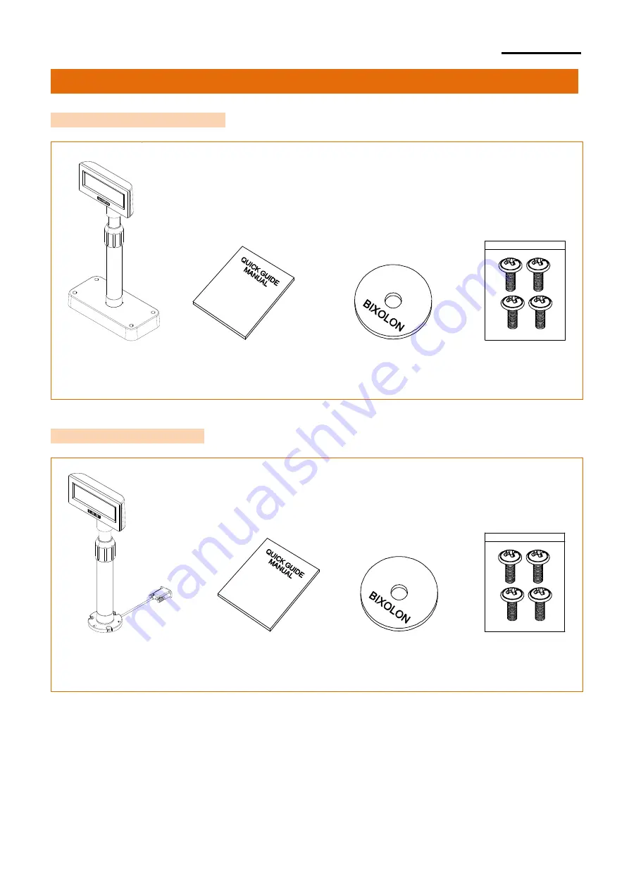
2. Unpacking
2-1 BCD-2000A/AU/DS Types
Display Set Installation Guide CD Screws x 4
(M3x10) Tapping
2-2 BCD-2000N/NU Types
Page 1: ...User s Manual BCD 2000 Customer Display Rev 1 02 http www bixolon com...
Page 2: ...upported 4 Rotation Angle Horizontal 180 Vertical 52 5step 5 Display Color Background Blue Characters White 6 Emulation ESC POS CD5220 It is advisable to read the contents of this manual carefully bef...
Page 3: ...ection Types Sizes 9 4 1 Connection Types BCD 2000A N DS WA WN WDS 9 4 2 How to Connect BCD 2000AU NU WAU WNU 9 4 3 Sizes 11 5 Features 12 5 1 Swivel 12 5 2 Tilting 13 6 Connection 14 6 1 Connecting D...
Page 4: ...unt BCD 2000WA WAU WN WNU WS BCD 2000A BCD 2000AU BCD 2000N BCD 2000NU BCD 2000DS BCD 2000WA BCD 2000WAU BCD 2000WN BCD 2000WNU BCD 2000WS All models can be easily mounted on a wall or desk using an e...
Page 5: ...Rev 1 02 5 BCD 2000 2 Unpacking 2 1 BCD 2000A AU DS Types Display Set Installation Guide CD Screws x 4 M3x10 Tapping 2 2 BCD 2000N NU Types Display Set Installation Guide CD Screws x 4 M3x10 Tapping...
Page 6: ...Rev 1 02 6 BCD 2000 2 3 BCD 2000WA WAU WS Types Display Set Installation Guide CD Screws x 4 M3x10 Tapping 2 4 BCD 2000WN WNU Types Display Set Installation Guide CD Screws x 4 M3x10 Tapping...
Page 7: ...directly without passing through the board Item Display Serial Standard Model BCD 2000N BCD 2000A How to Connect a Power Cable to the Serial Cable Connect an SMPS to the Serial Cable Jack Voltage Use...
Page 8: ...y Printer Item Display Serial Standard Model BCD 2000DS Standard Board Specifications Power Optional 24V 2 5A 24V 1 5A Cable Types Optional Serial Cable 9PM to 25PF Power Cable 3P to 3P Power Cable 3P...
Page 9: ...Printer 24VDC Power Connection 3 SMPS Display Printer 24VDC Serial Cable Connection 1 Host Display Printer Serial Cable Connection 2 Host Printer Host Display Misc A Power Supply Connector Output 24V...
Page 10: ...USB port on a PC 3 Turn on the PC and display The PC will automatically detect new hardware connected to the USB port 4 Once the driver is installed the display is ready to receive data Caution or War...
Page 11: ...02 11 BCD 2000 4 3 Sizes 4 3 1 Desktop Type 4 3 2 Wall Mount Type 4 3 3 Others 375mm 519mm 498mm 353mm 153mm 174mm 173mm 152mm 161mm 163mm 98mm 49mm 220mm 105mm BCD 2000A AU 76mm 26mm 32mm 76mm BCD 2...
Page 12: ...der so the body goes down Refer to the OPEN CLOSE indications on the product b Swivel the body to the angle you want c After adjusting the angle tighten the Nut Holder Keep the body from swiveling whe...
Page 13: ...want Please follow the instructions below to avoid damage or malfunction when installing the device It can be tilted up to 13 to each side with 4 levels and 5 positions Tilt max 52 Caution or Warning...
Page 14: ...ect Connection Pin 6 1 1 How to Install 1 Turn off the PC 2 Connect the display cable to the RS 232 port on the PC 3 Use a proper DC power adapter to connect the DC power 4 Turn on the PC and display...
Page 15: ...6 7 8 9 pin Name NC RXD TXD DTR GND DSR NC CTS NC Short Connection 6 1 3 DC Power Jack MAX 24VDC Caution or Warning Use only the genuine connection cable and adapter provided by the manufacturer The w...
Page 16: ...put 1 BCD 2000 connected to pass through Send data from printer to host 2 BCD 2000 connected independently Send data from DM to host 3 RXD Input Receive data from host Host DM 4 RTS Output Same as DTR...
Page 17: ...set signal to printer host printer Caution or Warning Use only the genuine communication cable provided by the manufacturer The warranty does not cover damage caused by the use of unauthorized cables...
Page 18: ...ol Switches 7 1 1 Location The Power and Brightness Control switches are located at the bottom of the display 7 1 2 Function Power Switch turns on off the power Brightness Control Switch adjust the br...
Page 19: ...e Enable 3 Parity Selection Odd Even 4 6 Data Rate 4 5 6 Data Rate 4 5 6 Data Rate 0 0 0 9 600 bps 1 0 0 115 200 bps 0 0 1 4 800 bps 1 0 1 57 600 bps 0 1 0 2 400 bps 1 1 0 38 400 bps 0 1 1 1 200 bps 1...
Page 20: ...Display is selected 1 3 4 Cursor display n 1 Cursor On 0 1 5 7 Reserved 8 Sleep mode selection n 0 Sleep mode off 0 1 2 MSW 2 BCD 2000 Setting Memory S W Function Default Content to be set Range to b...
Page 21: ...SC POS 0 15 2 3 4 5 Reserved 6 7 8 BCD 2000 2000K 3000 Command Emulation Memory Switch Emulation Remark MSW5 4 MSW5 3 MSW5 2 MSW5 1 OFF OFF OFF OFF ESC POS Note 1 OFF OFF OFF ON CD5220 OFF OFF ON OFF...
Page 22: ...is located inside the base unit Remove the PCB cover by pressing the hook on the base unit as shown in the image below Caution or Warning Close the PCB cover before operation Base Board CN1 J2 J1 CN2...
Page 23: ...tion CN2 2 Jumper 2 Can be used when Data Pass Through mode or Printer Disabled mode is selected Connection Mode JP2 Function Data Pass Through Default 1 2 4 5 Can be connected to a printer that does...
Page 24: ...ver Windows XP 32bit 64bit WEPOS 2003 Server 32bit 64bit 2008 Server 32bit 64bit VISTA 32bit 64bit Windows 7 32bit 64bit Windows 8 32bit 64bit Windows 10 32bit 64bit OPOS Driver Windows XP 32bit 64bit...
Page 25: ...normes class A d interference radio tel que specifier par ministre canadien des communications dans les reglements d interference radio Caution Some semiconductor devices are easily damaged by static...
Page 26: ...Rev 1 02 26 BCD 2000 Revision history Rev Date Page Description 1 00 10 05 17 New 1 01 12 28 17 20 21 Add New Emulation 1 02 26 07 18 24 Modified display area AA VA...